
ID : 5292
Selection of Screw Shaft Dia., Lead and Nut
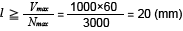
Selection of lead (l )
From the max. speed of DC motor
Select from among accuracy large lead products of 20 mm or longer lead.
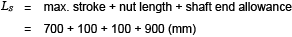
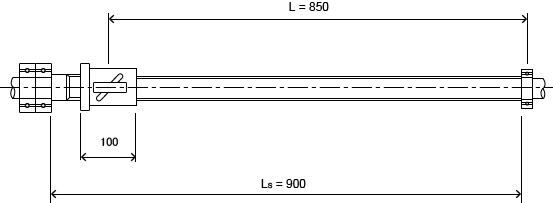
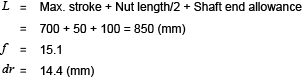
Temporary selection of thread length
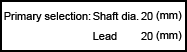
Selection of screw shaft dia.
Select the shaft dia. by checking the allowable speed with a high speed feed. The bearing support construction shall be of the most general fixing-support one.
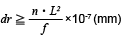
Dangerous speed
An examination is required for the ball screw speed not to resonate with the intrinsic number of vibrations of the screw shaft. The allowable speed shall be 80% or less of this dangerous speed.

a : Safety factor (a = 0.8)
E : Modulus of longitudinal elasticity (E = 2.06 X 10⁴(10 to the power of 4) kPa)
I : Minimum secondary moment of the screw shaft cross section

dr : Screw shaft minor dia. (mm) <See Dimension Table>
r : Specific weight of the material (r = 7.8 X 10⁻⁶(6-minex) kg/mm3)
A : Screw shaft cross-sectional area (A = πdr 2/4 mm2)
L : Distance between mounting points (mm)
f ,λ : Factor fixed by the mounting method of the ball screw
Support - support f = 9.7 (λ = π )
Fixing - Support f = 15.1 (λ = 3.927 )
Fixing - fixing f = 21.9 (λ = 4.730 )
Fixing - freedom f = 3.4 (λ = 1.875 )
Therefore, from equation (a)
dm・n value
Allowable speed is also regulated by dm⋅n value which shows peripheral speed (dm: center circle dia. of steel ball mm n: speed rpm).
Generally

Therefore,

Life forecast
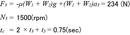
( When accelerating (1) (4) )
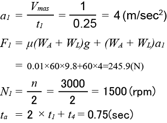
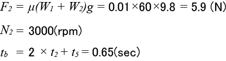
( At constant speed (2) (5) )
( When decelerating (3) (6) )
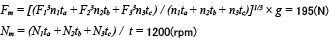
Average load Fn , Average rpm Nn
When shaft direction load is changed, find the average load which may give the life equal to the fatigue life under changing load conditions, and calculate the life.
When load and rpm are divided step-by-step
|
Step-by-step fluctuation load
|
Shaft direction load (kgf) |
Speed (rpm) |
Time in use or rate of time in use |
|---|---|---|---|
|
F 1 F 2 ٠ ٠ ٠ F n |
n 1 n 2 ٠ ٠ ٠ n n |
t 1 t 2 ٠ ٠ ٠ t n |
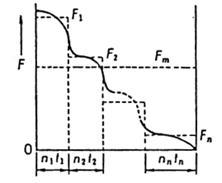
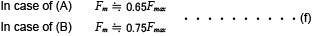
Average load F m can be achieved by the following equation.

And the average rpm can be achieved by the following equation.

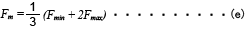
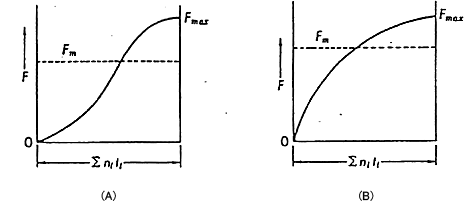
When load is changed almost linearly
Monotonous fluctuation load
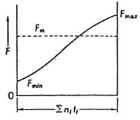
Average load F m can be approximately achieved by the following equation.
When load is changed like a sine curve
Average load F m can be approximately achieved by the following equation.
Therefore, from equation (c), (d)
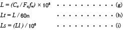
Life calculation
Fatigue life is generally shown by total rpm. Sometimes it is shown by total rotation time or total running distance. Fatigue life can be achieved by the following equation.
| Symbol | Meaning | Unit |
|---|---|---|
| Rated fatigue life | (rev) | |
| Life time | (hr) | |
| Running distance life | (km) | |
| Basic dynamic load rating | (N) | |
| Shaft direction load | (N) | |
| Speed | (rpm) | |
| Lead | (mm) | |
| Load coefficient (coefficient by operating condition) | - |
| Smooth running without shock | 1.0 - 1.2 |
|---|---|
| Normal running | 1.2 - 1.5 |
| Running with shock/vibration | 1.5 - 3.0 |
When selecting a ball screw, it is not economical to make its fatigue life uselessly long because the ball screw must be so much big. For reference, general target value of fatigue life is shown bellow.
| Term | Fatigue life (hr) |
|---|---|
| Machine tool | 20,000 |
| Industrial machine | 10,000 |
| Automatic controller | 15,000 |
| Measuring instrument | 15,000 |
Therefore, from equation (g), (h) (T clearance Ca = 7056 kgf)

ID : 5292