
ID : 209
Rotate
Function
To rotate a designated axial spin.
Syntax
Rotate reference rotary surface, rotary angle[, rotary center coordinates][, pose = rotary option][, static = rotation direction fixing option][, motion option]
Guaranteed Entry
- Reference rotary surface
- Specify a plane which is a base of the actual rotary surface where a robot passes through when actually operating.Use any of "XY","YZ","ZX","XYH","YZH","ZXH",(Vector Type, Vector Type, Vector Type) for designation. Refer to "Designating reference rotary surface".
- Rotary angle
- Designate the rotary angle (Deg) by Single Precision Real Number Type data. Target position option can be added to the rotary angle.
The rotation direction is decided based on the relation between the approach vector and the actual rotary surface. For details, refer to Rotation direction. - Rotary center coordinates
- Specify the rotary center coordinates by Vector type data.The line which is vertical to the actual rotary surface and passes through the rotary center coordinates can be the rotary center axis.
This can be omitted depending on the way of specifying the reference rotary surface.
For details, refer to How to specify the rotary center coordinates. - Rotary option
- Use "pose = 1" or "pose = 2" for designation. Refer to "Rotary option".
This is an optional value. This should be "pose = 2" if this is omitted. If you specify a value other than 1 or 2, the robot moves the same as when it is omitted. - Rotation direction fixing option
- Specify "static = [Disable]" or "static = [Enable]".
Specify enable/disable by integer type data.
[Enable]:True or an integer other than 0
[Disable]:False or 0
When "static = [Enable]" is specified, the direction of the rotary center axis is determined regardless of the direction of the approach vector, and the rotation direction is fixed.
This is an optional value. This should be "static = [Disable]" if this is omitted.
This option is enable only if "XY","YZ","ZX" or Flat surface with a given angle (specifying three points) is specified for the reference rotary surface. If "XYH","YZH","ZXH" are specified, it rotates on the Tool coordinate system. Therefore, it is clockwise rotation regardless of specifying this option. - Motion option
- A motion option can be specified.
Description
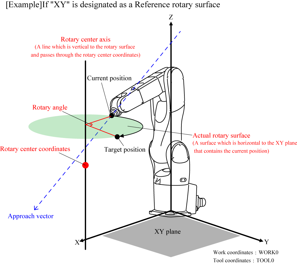
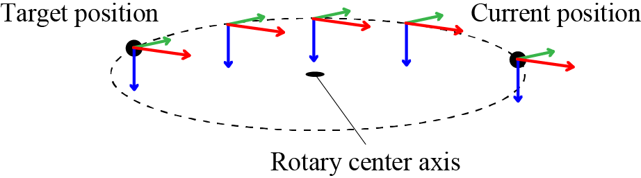
Robot moves on the actual rotary surface, by the specified rotary angle, in an arc. The actual rotary surface is parallel to the specified reference rotary surface and passes the current position.
The axis of rotation is a line which is vertical to the actual rotary surface and passes through the specified rotary center coordinates.
To execute this statement, the task must acquire robot axis control.
How to Specify the Designating reference rotary surface
There are ways to designate a reference rotary surface as described below.
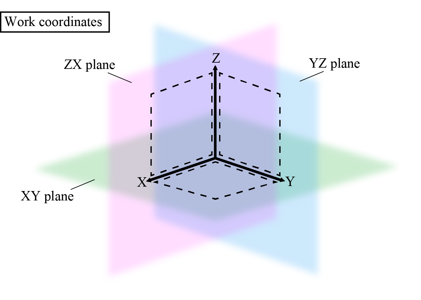
- A surface that is based on the currently selected work coordinate system: "XY", "YZ", "ZX"
- With the three axes (X, Y, and Z axis) on the current Work coordinate system, assume that a plane that consists of two of these axes is called a Plane A. The actual rotary surface is a plane which contains the current position and is horizontal to the Plane A.
XY represents the XY plane, YZ represents the YZ plane, and ZX represents the ZX plane.
Rotary center coordinates are omittable. This should be the origin of Work coordinate system (0,0,0) when omitted.
For motion examples of the specified XY plane, check here.
- A surface that is based on the currently selected tool coordinate system: "XYH", "YZH", "ZXH"
- With the three axes (X, Y, and Z axis) on the current Work coordinate system, assume that a plane that consists of two of these axes is called a Plane A. The actual rotary surface is a plane which contains the current position and is horizontal to the Plane A.
XYH represents the XY plane, YZH represents the YZ plane, and ZXH represents the ZX plane.
You cannot omit the rotary center coordinates. - Flat surface with a given angle: (Vector Type, Vector Type, Vector Type)
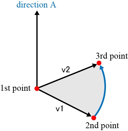
- On the base coordinate system, specify three points by Vector type data. Assume that a plane that consists of the three points is called a Plane A. The actual rotary surface is a plane which contains the current position and is horizontal to the Plane A.
Rotary center coordinates are omittable. The first vector value in vector type data that designate the reference rotary surface is assigned when omitted.
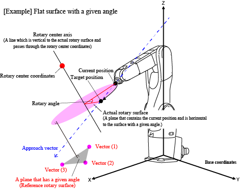
For motion examples of the specified flat surface with a given angle, check here.
Rotation Direction
The rotation direction is clockwise to the rotary center axis vector.
A rotary center axis has two vector directions. The effective vector direction is determined by the direction of the approach vector to the actual rotary surface.
For example, in the figure below, the rotary center axis has two vector directions; a direction A and a direction B.
In this case, if the current position is P1, the rotation direction is the rotation direction A because the approach vector faces to the direction A, viewing from the actual rotary surface P1.
On the other hand, if the current position is P2, the rotation direction is the rotation direction B because the approach vector faces to the direction B, viewing from the rotary surface P2.
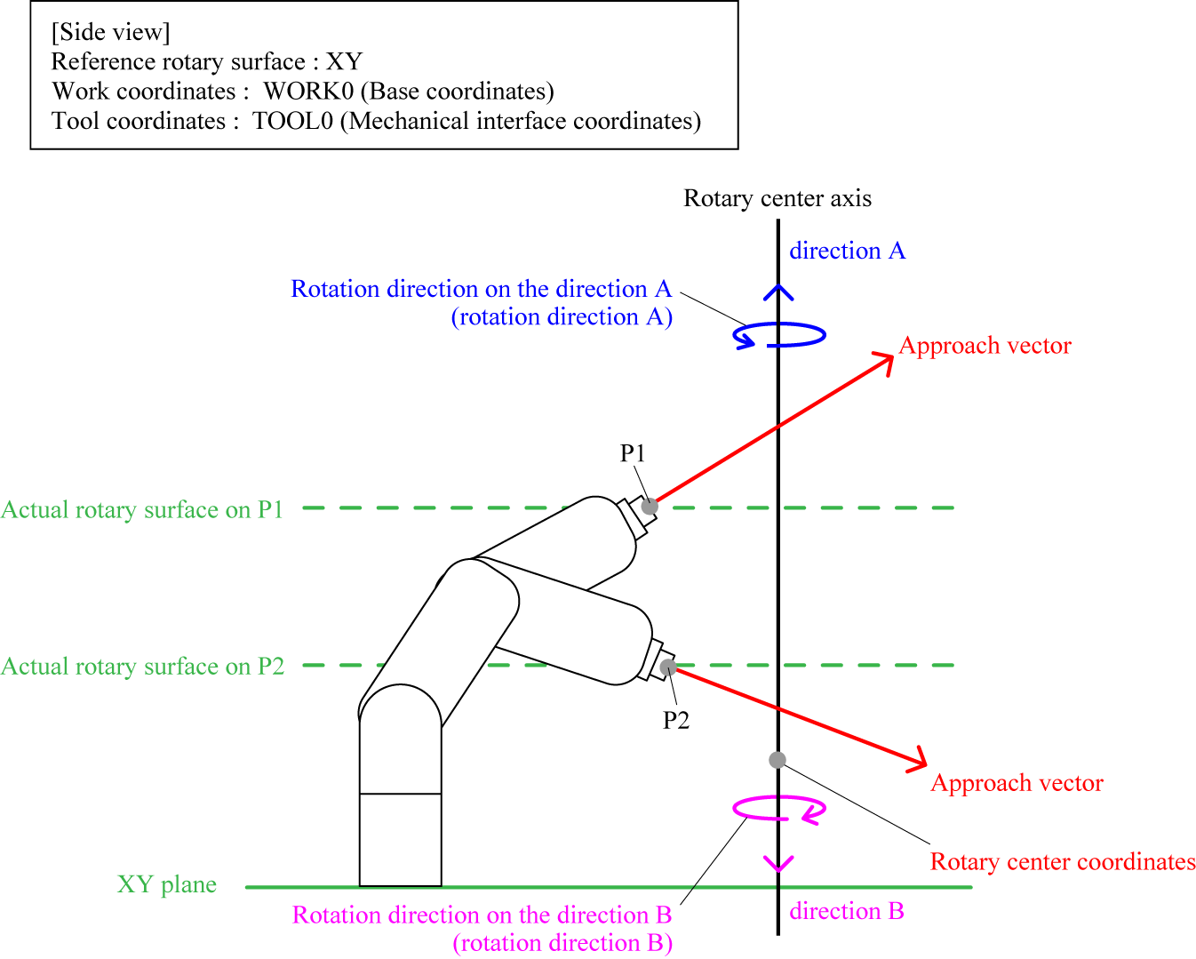
If the approach vector on the current position is horizontal to the actual rotary surface, it is impossible to determine the rotation direction. As a result, a robot may move in different direction even if the same motion is performed. In that case, change the current position and/or the condition of the actual rotary surface, or enable static. When "static = [Enable]" is specified, the vector direction of the rotary center axis is determined regardless of the direction of the approach vector. For details, refer to the following explanation.
When Specifying "static=[Enable]"
The vector direction of the rotary center axis is fixed regardless of the direction of the approach vector to the actual rotary surface. The vector direction of the rotary center axis is determined by the specified reference rotary surface.
How to Specify the Rotary Center Coordinates
The coordinate system of the rotary center coordinates differs depending on the rotary surface specified. Refer to the following table.
| Referencerotary surface to specify | Coordinate system | Omission of rotary surface entry |
|---|---|---|
| XY、YZ、ZX | Specify the coordinates on the current Work coordinate system. | Omittable. If the rotary surface is not specified, the origin of the current Work coordinate system will be the rotary center coordinate. |
| XYH、YZH、ZXH | Specify a coordinate on the current Tool coordinate system. | Not omittable |
| A plane with a given angle | Specify coordinates on the base coordinate system. | Omittable. If the plane is not specified, the first point (vector 1) on the given reference rotary surface that is expressed by the vector type data will be the rotary center coordinate. |
Designating Rotary Option
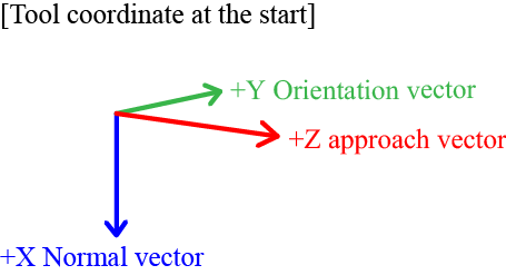
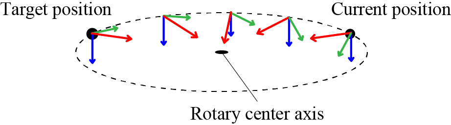
Rotary option specifies whether or not the posture is maintained according to the rotation. When "Pose = 1" is specified, the posture changes along with rotation. When "Pose = 2" is specified, the posture at the current position (start point) is maintained and rotation motion is performed for the track only.
- Pose = 1
 |
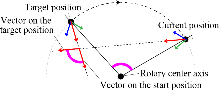 |
The above figure shows the left figure that is viewed from above the actual rotary surface. |
- Pose = 2
 |
Related Terms
Attention
Depending on the current robot position, an error may occur because some points on the motion path are not available.
In this case, change the current position and/or the condition of the rotary surface.
Example
'!TITLE "Rotary Motion of Axial Spin"
' Rotation motion by the angle value specified for axial spin perpendicular to the actual rotary surface
Sub Sample_Rotate

  Dim aaa As Position
  Dim bbb As Position

  TakeArm Keep = 1

  ' Assign the current position to aaa
  aaa = CurPos

  ' Rotate by 45 degrees on the axial spin perpendicular to the XY flat surface crossing the V[1] point
  Rotate XY, 45, V[1]

  ' Assign the current position to bbb
  bbb = CurPos

  ' Display initial position on the message output window
  PrintDbg aaa

  ' Display current position on the message output window
  PrintDbg bbb

End Sub
ID : 209
- Related Information
- Motion Examples of Rotate