
ID : 3219
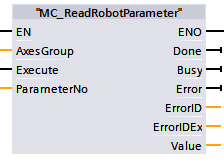
MC_ReadRobotParameter
To return general conditions of robot use from robot controller.
| Graphic expression | FB No. | FB category |
|---|---|---|
 |
FB2141 | Non motion |
Input parameter
| Parameter name | Data type | Valid range | Default | Omission (*) |
|---|---|---|---|---|
| AxesGroup | Integer | 1 or larger | 1 | No |
|
||||
| Execute | Boolean |
|
False | No |
|
||||
| ParameterNo | Integer | 1 or larger | 1 | No |
|
||||
(*) : For some parameters, entries can be omitted.
- Yes : Entry can be omitted.
- No : Entry required always.
Output parameter
| Parameter name | Data type / Description |
|---|---|
| Done | Boolean |
|
|
| Busy | Boolean |
|
|
| Error | Boolean |
|
|
| ErrorID | Word |
|
|
| ErrorIDEx | DWord |
|
|
| Value | Real |
|
Function description
Default values are different from robot types. The following shows an example of VS serie
| ParameterNo | Items | Unit | Default | Description |
|---|---|---|---|---|
| 1 | Mass of payload | g | 4000 | Mass of end-effector and object to be mounted at the end of the robot arm. |
| 2 | Payload center of gravity X | mm | 0 | X component of payload center of gravity (consisting of end-effector and object) |
| 3 | Payload center of gravity Y |
mm | 80 | Y component of payload center of gravity (consisting of end-effector and object) |
| 4 | Payload center of gravity Z |
mm | 100 | Z component of payload center of gravity (consisting of end-effector and object) |
| 5 | Payload moment of inertia Ix | kgcm² | 0 | Moment of inertia around X axis (consisting of end-effector and object) |
| 6 | Payload moment of inertia Iy | kgcm² | 0 | Moment of inertia around Y axis (consisting of end-effector and object) |
| 7 | Payload moment of inertia Iz | kgcm² | 0 | Moment of inertia around Z axis (consisting of end-effector and object) |
| 8 | Control set of motion optimization | - | 0 | 0: None 1: PTP 2: CP 3: PTP・CP |
| 10 | Floor-mount, or Overhead-mount |
- | 0 | 0: Floor-mount 1 : Overhead-mount 2 : Wall-mount (under-face) 3 : Wall-mount (Right-face) 4 : all-mount (Left-face) |
| 11 | Efficiency of gravity effect |
- | 0 | 0 : Gravity compensation feature disabled 1 : Gravity compensation feature enabled |
| 12 | DEFLECTION mode setting | - | 0 | Modify the robot arm's deflection caused by the gravity depending on the motion position, posture, load conditions, automatically. 0 : Disabled 1 : Enabled |
| 14 | Restoration of TOOL/WORK data | - | 0 |
If this option is enabled, once the controller turns ON, it operates with the same TOOL/WORK number as the controller turned OFF last time. (Note : This corresponds to "Restoration of TOOL/WORK data" of RC7M.) |
| 15 | Setting of TCP speed pattern | - | 1 | 0 : Depends on rotation motion 1 : Constant speed |
| 16 | Accel and decel setting at teach check | - | 1 | 0 : first root 1 : Square |
| 17 | Angle for position allowance (J1) | deg | 0.01099 | |
| 18 | Angle for positioning allowance (J2) | deg | 0.00879 | |
| 19 | Angle for position allowance (J3) | deg | 0.00997 | |
| 20 | Angle for position allowance (J4) | deg | 0.01099 | |
| 21 | Angle for position allowance (J5) | deg | 0.00845 | |
| 22 | Angle for position allowance (J6) | deg | 0.01758 | |
| 23 | Angle for position allowance (J7) | mm | 0.12207 | |
| 24 | Angle for position allowance (J8) | mm | 0.12207 | |
| 25 | Operation end time-out | ms | 5600 | When executing Move @E command or Move@C command, if the command is not finished within the specified time or specified pulse, time-over error occurs. |
| 26 | Control log mode | s | 10 | |
| 27 | Control log sampling time | ms | 8 | Sampling time of the control log Selection value:8, 16, 24, 32 ms |
| 34 | Positive software motion limit (J1) | deg | 170.000 | |
| 35 | Positive software motion limit (J2) | deg | 120.000 | |
| 36 | Positive software motion limit (J3) | deg | 151.000 | |
| 37 | Positive software motion limit (J4) | deg | 270.000 | |
| 38 | Positive software motion limit (J5) | deg | 120.000 | |
| 39 | Positive software motion limit (J6) | deg | 360.000 | |
| 40 | Positive software motion limit (J7) | mm | 500.000 | |
| 41 | Positive software motion limit (J8) | mm | 500.000 | |
| 42 | Negative software motion limit (J1) | deg | -170.000 | |
| 43 | Negative software motion limit (J2) | deg | -120.000 | |
| 44 | Negative software motion limit (J3) | deg | -120.000 | |
| 45 | Negative software motion limit (J4) | deg | -270.000 | |
| 46 | Negative software motion limit (J5) | deg | -120.000 | |
| 47 | Negative software motion limit (J6) | deg | -360.000 | |
| 48 | Negative software motion limit (J7) | mm | 0.000 | |
| 49 | Negative software motion limit (J8) | mm | 0.000 | |
| 50 to 57 |
Reduce Gain (J1 to J8) | % | 0 | Setting the reduce gain rate of axis (J1 to J8) |
| 60 | Setting of singularity avoidance mode | - | 0 | 0 : Disabled 2 : Enabled You can change the singularity avoidance level from "189: Setting of singularity avoidance level". |
| 78 | Ambient temperature | degC | 40 | Set in accordance with the ambient temperature. If in the place where temperature changes dramatically, set the expected maximum ambient temperature. Note If the ambient temperature setting is incorrect, robot may stop with an error. If the setting temperature is lower than actual ambient temperature, robot may be broken. |
| 82 | Pass Motion setting | - | 0 | Set the motion destination position at rebooting after stop processing execution during pass motion.
0 : Move to the destination position after pass motion |
| 83 | Positioning allowance of pass end | mm | 5 | Conditions to prevent to move to the previous destination position of pass motion. Set by the distance from the destination position. |
| 108 | Position for positioning allowance | mm | 0.100 | |
| 109 | Pose for positioning allowance | deg | 0.100 | |
| 110 to 117 |
Allowance for Position gap detection (J1 to J8) | deg | 10.000 | |
| 118 | Trajectory poses clear setting at TakeArm | - | 1 | Changes the validity of free curve viapoint clear process execution during TakeArm. 0 : Enabled 1 : Disabled |
| 119 | Disable emergency stop dual channel check | - | 0 | Specify whether to detect the inconsistency between emergency stop signals. 0 : Enabled |
| 120 | Emergency stop dual channel check cycle | s | 0.5 | Specify the insensitive time before the detection. This item is available when Safety IO-less specification is selected. |
| 123 | Disable protective stop dual channel check | - | 0 | Specify whether to detect the inconsistency between protective stop signals. 0 : Enabled |
| 124 | Protective stop dual channel check cycle | s | 0.5 | Specify the insensitive time before the detection. This item is available when Safety IO-less specification is selected. |
| 136 | Temperature Drift Offset | - | 1 | 0 : OFF 1 : ON |
| 137 | Path accuracy compensation mode | - | 0 | This function is for 4-axis robots only. 0 : Basic control 1 : For high speed |
| 141 | Manual mode setting | - | 1 | This option specifies the operation mode of the manual mode selected at the time of the controller start-up. 1 : Joint mode 2 : XY mode 3 : TOOL mode 4098: XY mode (without posture control) 4099: TOOL mode (without posture control) |
| 142 | TOOL number setting | - | 0 | This option specifies the TOOL number selected at the time of controller start-up. Tool number: 0 to 63 |
| 143 | WORK number setting | - | 0 | This option specifies the WORK number selected at the time of controller start-up. WORK number: 0 to 7 |
| 149 | Boundless Rotation(J6) | - | 0 | 0 : Disable 1 : Enable 2 : Enable Automatically adjust the current angle of the 6th-axis to within the range of plus or minus 360 degree when the robot stops. |
| 152 | Force sensor status | - | 0 | Enable this option when the force sensor is used in the system. 0 : Disable 1 : Enable |
| 153 | Speed setting for b-CAP Slave | - | 0 | For details, refer to the "4.7 Setting of the command speed limit and acceleration limit" of b-CAP Communication for RC8. 0 : Servo Limit 1 : Servo Limit (ExtSpeed) 2 : Command Limit 3 : Command Limit (ExtSpeed) |
| 171 | Frange position encoder value check motion judgment mode | - | 0 | 0 : Immediate Execute the next line immediately once the tool end arrives the target position. 1 : Speed Execute the next line under the condition that the tool end arrives at the target position with the current speed and then is expected to remain within the target position after a specified time passes. 2 : Time Execute the next line under the condition that the tool end remains within the target position during the specified time period after arriving at the target position. |
| 172 to 179 | Each axis encoder value check motion judgment mode | - | 0 | 0 : Immediate Execute the next line immediately once the tool end arrives the target position. 1 : Speed Execute the next line under the condition that the tool end arrives at the target position with the current speed and then is expected to remain within the target position after a specified time passes. 2 : Time Execute the next line under the condition that the tool end remains within the target position during the specified time period after arriving at the target position. |
| 180 | Frange position encoder value check motion judgment time | ms | 16 | Set the time to be used for the judgement of Speed or Time on the Frange position encoder value check motion judgment mode. |
| 181 to 188 | Each axis encoder value check motion judgment time | ms | 16 | Set the time to be used for the judgement of Speed or Time on the Each axis encoder value check motion judgment mode. |
| 189 | Setting of singularity avoidance level | - | 0 | Change the method of the singularity avoidance. 0 : based on the figure at the starting and arrival position 1 : based on the figure at the starting and arrival position (except for Single, Double, Triple of the J4 and J6) |
| 190 | BASE number setting |
- | 0 | This option specifies whether the selected BASE number will be enabled at the time of controller start-up. 0 : Disable 1 : Enable |
| 215 | HighPathAccuracy setting | - | 0 | This option specifies whether the HighPathAccuracy setting will enable or disable. 0 : Disable 1 : Enable |
| 217 | Vibration Control M setting | - | 0 | This option specifies whether the Vibration Control M setting will enable or disable. 0 : Disable 1 : Enable |
| 218 | Display easy setting on start-up | - | 1 | Specify whether the Easy setting dialog is displayed at the controller startup or not. 0 : Not displayed 1 : Display (Default) |
| 220 | Payload command setting | - | 0 | This option specifies how the payload command works when an argument of the command (the center of gravity and/or inertia) is omitted. 0 : 0 is entered 1 : currently entered value is maintained. |
| 221 | FoceSensorPayload command setting | - | 0 | This option specifies how the FoceSensorPayload command works when an argument of the command (the center of gravity and/or inertia) is omitted. 0 : 0 is entered 1 : currently entered value is maintained. |
| 225 | Motion optimization Additional joint sync compatible mode (Version 2.4.* or higher) |
- | 1 | This option specifies the robot behavior when Extended-joint option for target position is used if Optimal speed control function is set to control set 1 or Control set 3. 0 : Ver 2.4.0 or more 1 : Less than Ver.2.4.0 |
253 |
Use a start point in spline curve (Version 2.7.* or higher) |
- | 0 | Sets whether to check if the robot exists in the start point of free curve interpolation motion when MoveS starts. If this parameter is [1:Enable], an error occurs unless the robot exists in the start point of free curve interpolation motion. Also, if this parameter is [1:Enable], you can select free curve moving method and motion Direction from the path point setting window. For details, refer to the "Path Points Confirmation Window" of "Operation Procedure for the Free Curve Motion." 0 : Disable1 : Enable |
264 |
Move speace change for Hanging type (Ver.2.8.0 or higher) |
- | 1 | Adjusts the motion range of the HSR series overhead mount type. Description of adjustment : To avoid the contact between the shaft edge and bellows portion and the base area. For details, refer to "HSR Series; Overhead-mount." 0 : Disable |
Attention
-
ID : 3219