
ID : 3335
Dual Arm Control Function-Specific Programming and Setting
This page describes the dual arm control function-specific information in the following categories.
EMU is option software (paid software) that enables the simulation of multiple Denso robots.
PacScript Command
-
How to specify a robot in robot motion command
-
To use a robot motion command, you need to specify a robot (Robot0 or Robot1) where the command is executed to.
Write the robot name of the target robot just before the robot motion command.
For example, to execute Move command for Robot0, write as follows.
Robot0.Move P, @[0] P[0]This is the same as the cooperative function. For information about how to specify a robot in other commands, refer to "Commands that Need to Specify a Robot" in "Command" in the "COOPERATIVE CONTROL FUNCTION GUIDE".
Some commands are executed for all robots. For details, refer to "Commands that Target to All Robots" in "Command" in the "COOPERATIVE CONTROL FUNCTION GUIDE". However, only SysState command is different from the above-mentioned link page. The specification of SysState command is the same for the single-axis robot operation.
-
Joint number in the application of "MC8 series-controlled robot × 2 Internal joint only"
-
In this combination, the joint number of Robot1 is different from the joint number of the motor connector that is actually connected to the MC8 series motion controller (hereafter, MC8 series). Suppose that you create the following system structure.
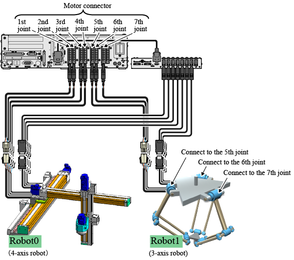
In the figure above, each motor on Robot1 connects to the 5th-, 6th- and 7th-joint of the motor connector on the MC8 series. However, in Robot1 project data, these joints are treated as the 1st-, 2nd-, and 3rd-joint from the smallest joint number ("5th-joint") of motor connector.
Also, these joint numbers (1st-, 2nd-, and 3rd-joint) are used in the program as well. For example, to move a motor that connects to the 5th-joint of the motor connector with Drive command, specify the 1st-joint as the following shows.
Robot1.Drive (1, 43)This idea is the same at the error occurrence. If an error occurs on a motor that connects to the 5th-joint of the motor connector, the error number and error message are issued as the 1st-joint.
On the error display window and the error log window, the error target robot name is displayed. This is the same as the cooperative control function-used operation. For details, refer to "Error Display And Error Log Display" in the "COOPERATIVE CONTROL FUNCTION GUIDE".
The joint number of the motor connector is determined by the motor capacity. For details, refer to "Caution for Wiring" in the "EXTENDED-JOINT MANUAL".
Operation and Setting with a Teach Pendant
Error display and error log display
-
On the error display window and the error log window, the error target robot name is displayed. This is the same as the cooperative control function-used operation. For details, refer to "Error Display And Error Log Display" in the "COOPERATIVE CONTROL FUNCTION GUIDE".
Display of Easy Setting
-
At the RC8 series robot controller startup, the easy setting window for Robot0 is displayed. Note that the easy setting window for Robot1 is not displayed. However, you can use the easy setting for Robot1 by specifying Robot1 as a leader robot and then opening the easy setting window from the following operation path.
Operation path : [F2 Arm] - [F6 Aux] - [F1 Config] - [F6 Easy Setting] For information about how to specify a robot as a "leader", refer to "Control with a Teach Pendant" in "Concept of the Dual Arm Control Project".
Note that the easy setting-available robots are limited. For details, refer to "Easy Setting (Teach pendant)" in the "OPERATION GUIDE".
How to select an extended joint for operation
-
To operate an extended joint from the teach pendant, normally, press the [Robot selection] button to select an extended joint as an operation target. This operation is the same for the dual arm control function. However, the window displayed after you press the [Robot selection] button is different from the normal operation.
The following window appears.
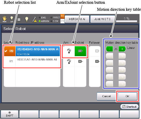
First, specify the robot that the operation target extended joint belongs. To specify the robot, from the robot selection list, select the target robot.
Next, from the "Arm/ExJoint selection button", select an extended joint (a motor icon). In the "Motion direction key table", the extended joint number is displayed and the buttons used to control the target extended joint turn green.
After the above process, press [OK] to confirm the setting change. The operation target has been changed to the extended joint.
Exclusive control function/Cooperative control function setting
-
When the dual arm control function is used, if you use the exclusive control function or the cooperative control function, the communication between two robot controllers (including RC8 series robot controller (hereafter, RC8 series) and MC8 series motion controller (hereafter, MC8 series) is not supported. One RC8 series or MC8 series controls two robots with the exclusive control function or the cooperative control function. Therefore, some configurations of each function are different from the normal operation.
Exclusive Control Function When the dual arm control is not used, the window displayed from the following operation path is [Exclusive Communication]. However, when the dual arm control is used, the system message to switch enable/disable of the exclusive control function is displayed.
Therefore, you don't need to set some parameters that are normally done on the exclusive communication window (such as Exclusive control IP (0), Exclusive control waiting timeout).
Operation path : [F2 Arm] - [F6 Aux] - [F11 Exclusive Control] - [F2 Exclusive Comunication] The button at the end of the above operation path ([F2 Exclusive Comunication]) will be displayed as [F2 Exclusive Setting].
Default setting is [Disable]. Before you use the exclusive control function, change the setting to [Enable] from this button.
Cooperative Control Function Any cooperation settings (such as cooperative controller configuration and cooperative control communication mode) made by the following operation path are not required.
Operation path : [F6 Setting] - [F9 Cooperation] The button at the end of the above operation path ([F9 Cooperation]) is not displayed.
Robot-disable setting
-
In the dual arm control, even if you retry teaching or change robot program for one robot only, you need to connect both robots to the RC8 series robot controller (hereafter, RC8 series) or the MC8 series motion controller (hereafter, MC8 series), otherwise, an error occurs.
To avoid error occurrence when only one robot connects to the RC8 or MC8 series, perform the robot-disable setting.
Set the login level to "Maintainer" and then follow the operation path below. [VRC Setting] window appears.
Operation path : [F6 Setting] - [F2 System Info] - [F6 VRC Setting] Among the following parameters in the [VRC Setting] window, enter "1" (disable) in the parameter of robot that you do not connect to.
No. Item 79 Robot0 Enable/Disable Setting 80 Robot1 Enable/Disable Setting After the setting, if you reboot the RC8 or MC8 series, the connection error for the unconnected robot will not occur.
If you connect the unconnected robot again, return to the original setting.
Dual arm control function-disable setting
-
To use only Robot0 in the normal operation (one robot-one controller operation), perform the dual arm control function disable setting.
The button at the end of the below operation path ([F1 Enable/disable]) is a button to enable/disable the dual arm control function.
Operation path : [F6 Setting] - [F10 Dual arms] - [F1 Enable/disable] Default setting is "Enable". Once you set this parameter "Disable", and then reboot the RC8 or MC8 series, only Robot0 works. In this state, the connection error does not occur if Robot1 does not connect.
EMU
3D view of Robot0 and Robot1
-
When you add dual arm control project data to an EMU project, the robots of Robot0 and Robot1 will be displayed in the 3D view. In this case, you must select Robot0 project file to add. If you select Robot1 project file, the 3D view will display Robot1 only.
The way to add dual arm control project data to an EMU project is the same way when you add cooperative control function project data to an EMU project. Refer to "Adding a Robot to EMU" in the "COOPERATIVE CONTROL FUNCTION GUIDE".
For information about folder structure of the dual arm control project data, refer to "Control with WINCAPSIII" in "Concept of the dual arm control project".
ID : 3335