
ID : 5092
Auto Gain Tuning Procedure
The robot controller performs acceleration/deceleration operation of the extended-joints according to the default pattern preset in the controller.
Based on the motion of the extended-joints in that operation, the controller will estimate the inertia of payload and set the appropriate gain automatically.
To implement auto gain tuning, your optional mechanism to be connected to the extended-joint motor should satisfy the requirements given below.
Otherwise, some errors may occur and the auto gain tuning process may be interrupted.
Do not approach or stay around the motion range of the target axis.
To the Auto-gain tuning, robots may move faster than the manual operation in the normal condition.
- If the AutoPositionClear is enabled, disable it.
- For safety motion specification, temporarily disable the monitoring function. For implementation, refer to "Auto Gain Tuning "of "Effects on the Existing Functions "in RC8A SAFETY MOTION SPECIFICATION MANUAL.
Requirements for implementing auto gain tuning
- The inertia of payload should be within the motor specifications and should not deviate greatly.
- The rigidity of the torque transmission mechanism (including motor and coupling) to be connected to the extended-joint motor should be high.
- The backlash in the torque transmission mechanism should be minimized.
- Rotating the motor in CCW and CW directions alternately two times each direction should result in no problem.
Auto gain tuning procedure
This operation is available for "Maintainer."
1
Turn the motor power on.
If the robot is in Auto or Teach check mode, switch to Manual mode.
2
Get out of the motion range so that there will be no problem even if the motor rotates in CCW and CW directions alternately two times each direction.
3
Display the Joint Setting window.
Press Top Screen — [F2 Arm] — [F12 Maintenance] — [F10 Joint Settings]
4
Press [F7 Auto Gain Tuning].
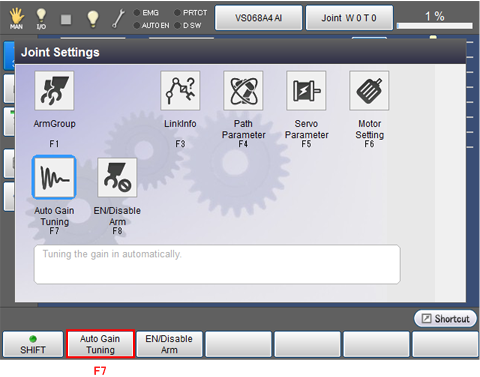
Auto gain tuning setting window appears.
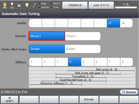
5
Choose the joint number that should undergo auto gain tuning.
The following example is the display when the 7th axis is selected.

6
Select the motor rotation direction.
The following example is the display when the negative direction is selected.
7
Select whether the gravity offset torque should be enabled or disabled.
The following example is the display when the gravity offset torque is enabled.
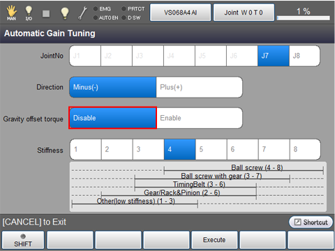
If an unbalanced load applies to the motor, be sure to enable the gravity offset torque.
If you enable the gravity offset torque for auto gain tuning, the controller will automatically calculate the torque offset included in servo configuration parameters. On the Joint Settings window, press [F5 Servo Parameter] to call up the servo configuration parameters window and then press OK to save the calculated torque offset value.
8
Select the mechanical stiffness, referring to the stiffness reference values listed below.
The following example is the display when "4" is selected.

| Types of Torque Transmission Mechanisms | Mechanical stiffness |
|---|---|
| Ball screw | 4 to 8 |
| Ball screw with gear | 3 to 7 |
| TimingBelt | 3 to 6 |
| Gear/Rack & Pinion | 2 to 6 |
| Other low stiffness | 1 to 3 |
9
Press [F4 Execute].
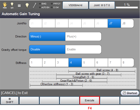
The following system message appears.
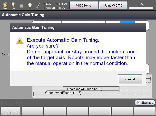
When pressed [OK] button of the teach pendant while holding down deadman switch, auto gain tuning will start.
Hold down deadman switch and [OK] button of the teach pendant through all processes of auto gain tuning.
Releasing either one or both of them will interrupt auto gain tuning.
- During auto gain tuning, do not press any key on the teach pendant except for the deadman switches. Doing so will interrupt auto gain tuning.
- If the joint motion has been set to [2: Enable encoder only] on the servo configuration parameters window, then the error message "Not executable" will appear during auto gain tuning.
10
The motor rotates in CCW and CW directions alternately two times each direction in two sequences to calculate a temporary servo loop gain.
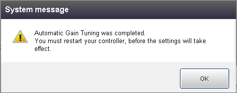
After that, the motor will repeat the sequence up to 8 times to fine-tune the gain. If the gain is fixed within the eight sequences, auto gain tuning will complete.
Once the auto gain tuning completes, the following message appears. Restart the controller.
- For a boundless rotation joint, CALSET needs to be performed after each auto gain tuning, which deletes CALSET values.
- After eight sequences of the above fine tuning operation, any of the following messages may display:
- [Tuning result did not converge.]
- If warning messages displays but there is no problem with the joint motion, then finish the gain tuning. If any abnormal noise or vibration is noted and there are some problems with the motion, then change the mechanical stiffness. After that, retry auto gain tuning or proceed to manual gain tuning.
-
If you set higher mechanical rigidity for transmission mechanism having lower rigidity and vise versa, then an error may occur during auto gain tuning. Change the mechanical rigidity setting and retry auto gain tuning.
ID : 5092