
ID : 1079
The Setting of the Deadman Switch Linkage Function
Operation path : [F6 Setting] - [F3 Pendant and Panel] - [F7 DSW interlock]
Set the deadman switch linkage function.
When pressing [F7 DSW interlock], [DSW interlock] screen is displayed.
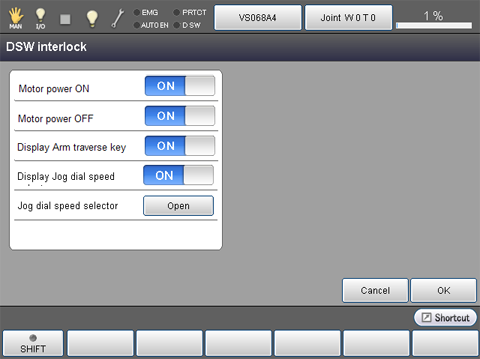
| Keys other than function keys | |
|---|---|
| Motor power ON | When this option is enabled, motor power turns on at the timing of pressing the deadman switch in manual or teach check mode. |
| Motor power OFF |
When this option is enabled, motor power turns off at the timing of releasing the deadman switch in manual or teach check mode. |
| Display Arm traverse key | When this option is enabled, the arm traverse key is displayed in the right side of the display during pressing deadman switch in manual or teach check mode. |
| Display Jog dial speed | When this option is enabled, you can change the robot speed to the custom speed value by the jog dial during the arm traverse key is displayed (a state of deadman switch is pressed) in manual or teach check mode. |
| Jog dial speed selector | Once [Open] button is pressed, the [Aux] window that sets the custom speed values will be displayed. |
For the Mini pendant, you can set the motor power ON/OFF-linkage with the parameter setting of WINCAPSIII. (This is available Var 1.8.* or later)
No.19: Interlock motor off and deadman SW (0: Enable, 1: Disable) (This item is displayed only when the Safety I/O-less specification is used)
No.20: Interlock motor on and deadman SW (0: Disable, 1: Enable)
For details about the way of setting, refer to "Configuring Parameters" of WINCAPSIII GUIDE.
ID : 1079