
ID : 2484
Robot Position Monitoring (RPM)
Function
This function monitors if the monitoring point on the robot does not go over the motion area.
If the monitoring point exceeds the specified range, SS1 function is activated. The robot stops its motion and the motor power turns off. Robot Position Monitoring is not a function that guarantees that respective monitoring point does not go over the monitoring area.
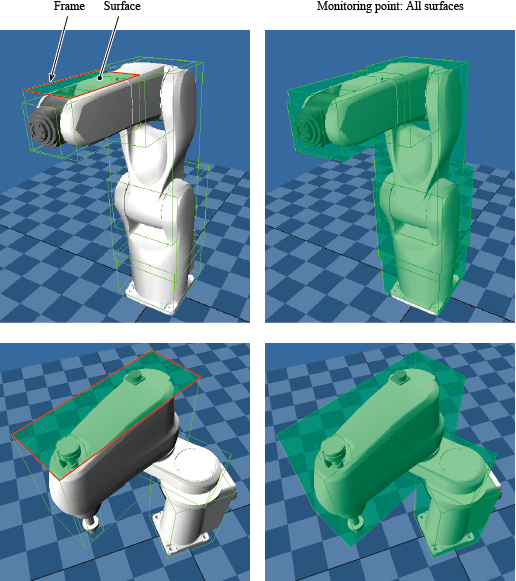
The monitoring point is the following location.
- Surface formed by frame surrounding the robot arm
There are two types of restricted areas as follows.
| Area | Description |
|---|---|
| Permanently restricted area | Permanently monitor if the robot exists within the specified area. |
| Temporary restricted area | The monitoring of this area can be enabled/disabled by Monitoring area N disable input (N represent a number from 0 to 3). |
Use Conditions
| Input signal | Monitoring disable input (effective only in the Manual mode), Tool number input N (N represent a number from 0 to 3), Monitoring area N disable input (N represent a number from 0 to 3) |
|---|---|
| Output signal | RPM output |
| Monitoring target | Robot axis, Extended-joint |
| Monitoring area setting | Permanently restricted area : Users must set this area. This area must enclose the entire robot. Temporary restricted area : Users optionally set this area. |
| Reaction time | 50 ms (Max) |
| Process Safety Time (PST) | 100 ms |
| Operation mode | Auto mode, Manual mode |
| Timing to start the function |
|
Note 1: To use Monitoring disable input, the safety parameter [15 : Monitoring disable input setting] needs to be [1: Enabled]. For details, refer to "Monitoring Disable Input".
How to Use
Specifying the Tool Number
Specify a Tool number with "Tool number input 0" to "Tool number input 3" of the Motion I/O input. Each Tool number input represents one bit of binary data. One Tool number consists of four bits.
Example : To specify TOOL1, turn ON the "Tool number input 0" and turn OFF the rest of Tool number inputs.
Specifying the Temporary Restricted Area
Monitoring area N disable input of Motion I/O input switches enable/disable the monitoring of the respective temporary restricted area.
A temporary restricted area whose "Monitoring area N disable input" turns ON is not monitored. Once the "Monitoring area N disable input" turns OFF, the monitoring starts.
Simulation with WINCAPSIII
Start a robot program on WINCAPSIII and can check whether a monitoring point is in the RPM monitoring area or not.
Because the collision detection is performed every robot control interval, display speed of robot motion will be slower.
This function is available for controllers in Ver.2.7.* or higher.
Perform the simulation by using the project that the monitoring area is set.
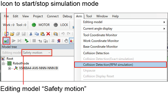
When performing the simulation, the following condition needs to be fulfilled with WINCAPSIII.
- Execute the simulation mode with the editing model is in "Safety motion."
Operation path : [Arm menu] - [Collision Detection(RPM simulation)]
Execute the program with the check of Collision Detection (RPM simulation) is selected. When RPM function detects collision while the program is executed, an error will occur.
Attention
- If a robot is mounted on an extended-joint, the robot position is offset by the travel distance of the extended-joint.
-
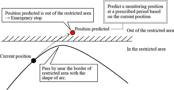
If pass by near the restricted area, an error may occur. If an error occurs, the following shows the ways of avoiding errors.
- Pass by away from the border of restricted area when passing by near the border of restricted area. (Adjust the current position, the target position, and the ways of motion etc.) .
- Reduce the speed when passing by near the border of restricted area.
ID : 2484