
ID : 5304
System Configuration
System Configuration
Connect motor cables with motor connectors on the MC8 series directly, as shown below. Encoder cables are connected to the MC8 series through the encoder HUB.
The SLOT number of the motor connector to be connected with the motor cable is designated before shipment.
The allowable combination of the controller's axes and motor types is printed in the label on the top of the controller. Please check that before establishing connections.
- For precautions on connections, refer to "Connect Cables to the Robot Controller" on the "Extended-joint Manual".
- The total length of an encoder cable for each axis between a connection port of the encoder HUB and a connection port of the motor shall be 16meter or less. The total length of a motor cable of each axis between a connection port of the controller and a connection port of the motor shall be 16meter or less. The total length of all axes is 96m at the maximum.
- For safety reason and to prevent damage to the devices, disconnect the power cable of the controller or shut down the power supply to the controller from the facilities before disconnecting or connecting cables.
- The contact current may exceed 3.5 mA, depending on the connection condition of the MC8 series system.
Before connecting the power cable, be sure to connect a ground wire (green-yellow and 2.5mm^2 or larger size) to the earth terminal at the front of the MC8 series system. - Components used in this system are not Dust- & Splash-proof type. These components can not be used in the environment which requires Dust- & Splash-proof type.
Models Except UL-Listed Ones
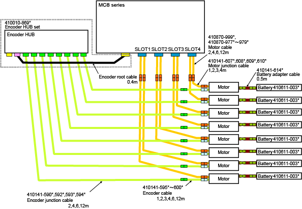
Click on the link to view the magnification. (PDF:145KB)
UL-Listed Model
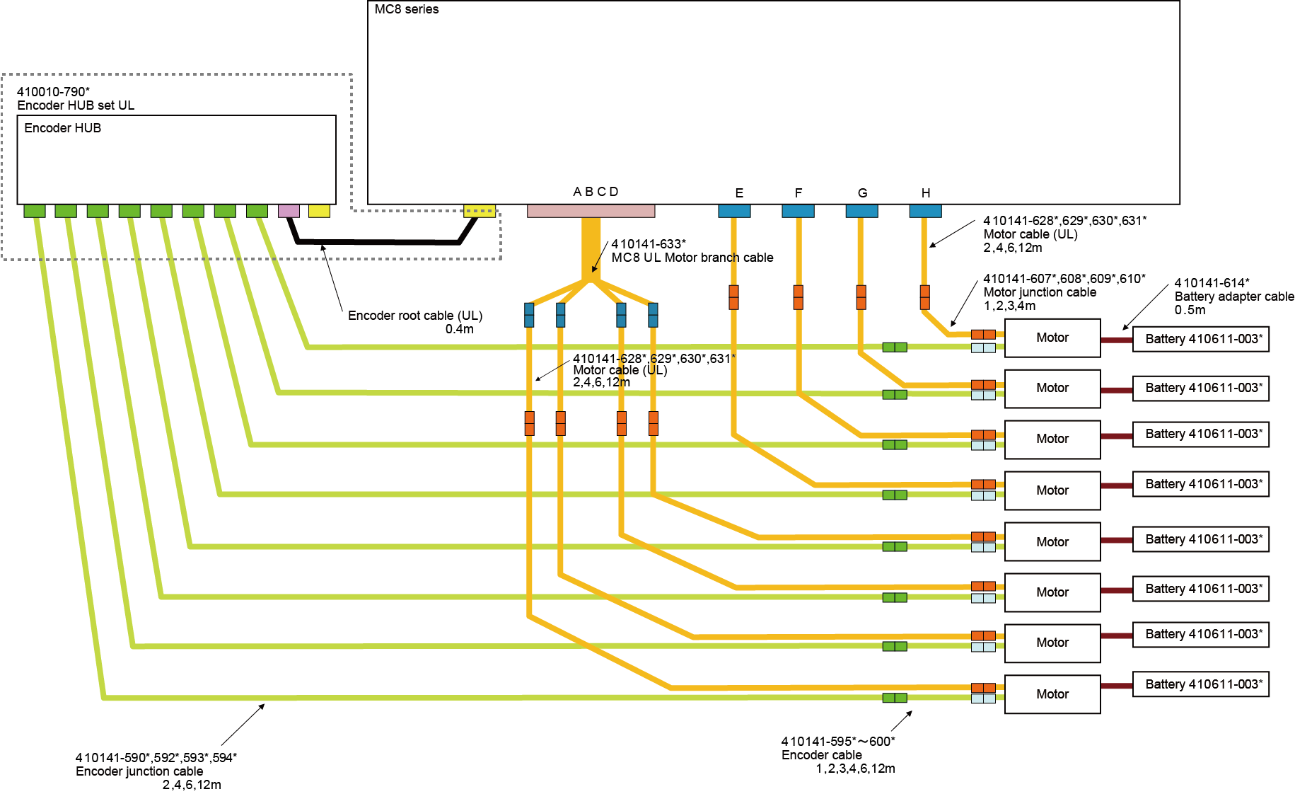
Click on the link to view the magnification. (PDF:124KB)
Controller
Names and External Dimensions of the Controller Components
Names and external dimensions of each parts of the MC8 series controller is the same as RC8 series robot controller.
For MC8A, refer to "Name of Each Section of Controller" and "Outer Dimensions" on the RC8A robot controller; for MC8, refer to "Name of Each Section of Controller" and "Outer Dimensions" on the RC8 robot controller.
| Title | Link | |
|---|---|---|
| Name of Each Section of Controller | MC8A | Parts Names of RC8A Controller |
| MC8 | Parts Names of RC8 Controller | |
| Outer Dimensions | MC8A | Standard, Safety Motion |
| MC8 | Standard, Safety-I/O less | |
Specification of the MC8 Series Controller
Specifications of MC8 series controller are same as the RC8 series robot controller except for the following items.
| Item | Specification |
|---|---|
| Allowable input voltage range | Three-phase, 200VAC-15% to 240VAC+10% |
| Control system | CP 3-dimension linear, 3-dimension circular (for Cartesian coordinate robot) |
For MC8A, refer to "Section of Controller" on the RC8A controller; for MC8, refer to "Specification of Controller" on the RC8 robot controller.
| Title | Link | |
|---|---|---|
| Specification of Controller | MC8A | Standard / Safety Motion, Safety I/O-less |
| MC8 | Standard, Safety-I/O less | |
I/O Allocation
I/O allocation of the MC8 series is the same as that of the RC8 series robot controller. For information about I/O allocation of the RC8 series, refer to "General Information about the Interface".
Note that the I/O allocation of Mini I/O is different between RC8 and RC8A. For MC8A, refer to "RC8A MINI I/O MANUAL", for MC8, refer to"RC8 MINI I/O MANUAL".
Drive Capacity of MC8 Series
The motor capacity that can be driven by the MC8 series is as listed below.
| MC8 series | Motor capacity | Total drive capacity |
|---|---|---|
| 1st to 8th axes | 1000W max./axis | 3000W max. |
Use AC servomotors specified in this manual. The total drive capacity does not change even when optional extended-joints are in use.
Errors at the Robot Operation
When errors occur at the robot operation (overload, excessive deviation, BUS under voltage), adjust the following items, or follow the instructions of "the error code list".
- Increase the waiting time before and after the robot motion.
- Reduce speed or acceleration.
Encoder HUB
The encoder HUB is the same as the one used for the extended-joint support controller.
For details, refer to "Encoder HUB" on the "Extended-joint Manual".
Motor
Available AC servomotors on the MC8 series are the same as that used for the extended-joint support controller.
For details, refer to "Engineering Design of Servo Mechanism", "Choosing AC Servo Motors" on the "Extended-joint Manual".
ID : 5304