
ID : 1991
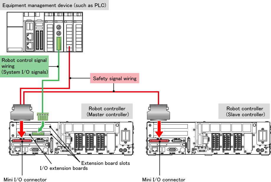
Wiring between an I/O Extension Board and the Equipment Management Device
To communicate system I/O signals through an I/O extension board, safety signal wiring must be also connected to Mini I/O.
Refer to the figure below.
| I/O extension board |
For example, DeviceNet slave board, CC-Link remote device board. For details, refer to "Overview of I/O Extension Boards".
|
||||
|---|---|---|---|---|---|
| Safety signal wiring | For details, refer to "Robot Controller Requirements and Safety Signal Wiring". |
||||
| System output signal | Some of system output signals output the logical AND or OR of both the master and slave controller states. For details on system output signals in each allocation mode, refer to the reference in the table below.
|
ID : 1991