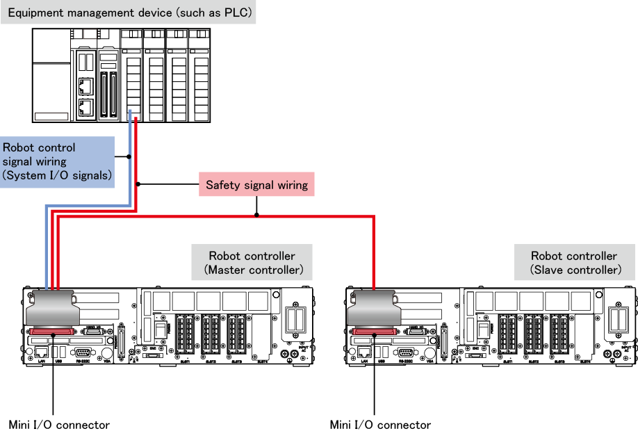
Wiring between Mini I/O and the Equipment Management Device
To communicate system I/O signals through Mini I/O, wire the robot control signals, as well as safety signals, to the Mini I/O connector.
Refer to the figure below.
| Safety Signal Wiring |
For details, refer to "Robot Controller Requirements and Safety Signal Wiring". |
| System output signals |
Some of system output signals output the logical AND or OR of both the master and slave controller states.
The details of system output signals are as follows.
| Signal name |
State to be output |
| Mini I/O dedicated mode signals |
Robot Running |
Master |
| Robot Error |
OR |
| Robot Initialized |
AND |
| Auto Mode |
Master |
| Operation Preparation Completed |
AND |
| Battery Warning |
OR |
| Command Processing Completed |
Master |
| Continue start Permission |
| CPU Normal |
Each state |
| Safety-circuit signals |
Pendant Emergency Stop (output) |
| Deadman SW (Enable SW output) |
STO Monitor (output)
(RC8A only) |
Auto Mode Mutual Monitoring (output)
(RC8A only) |
Contactor Contact Monitor (output)
(RC8 only) |
| Signals that can be used by the parameter settings |
Running Stop Processing |
OR |
| Robot controller startup completed |
| Robot Running (Position designation) |
| Robot Running (Encoder) |
| Change Battery |
| Motor OFF indicator |
- The following information is shown in "State to be output" in the table above.
| State description |
Indication |
| Logical AND of the master and slave controller state |
AND |
| Logical OR of the master and slave controller state |
OR |
| Master controller state |
Master |
| The states of the master and slave controllers are output from their respective robot controllers. |
Each state |
- For signals that can be used by the parameter settings, refer to "Status Output with User Output Ports".
|
