
ID : 2478
Wire Connection Required for Start-Up of the Robot
This section shows the minimum wiring connection required for the installation of the Safety motion specification robot unit. These wirings are necessary to turn on the motor power of a single robot unit and to perform Auto or Manual mode operation.
Input signals of the safety circuit are important for safety. Be sure to configure these circuits with contacts as shown below, observing the notes given below.
Configuration of Mini I/O input
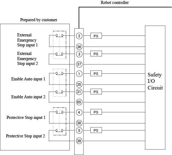
For the overall configuration of a safety circuit, refer to the Mini I/O MANUAL "[NPN type] Safety Circuit of RC8A" or "[PNP type] Safety Circuit of RC8A".
Configuration of Motion I/O input
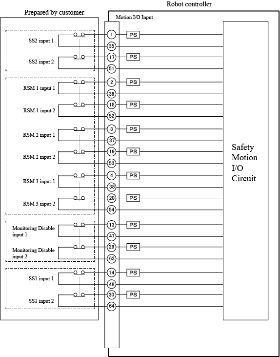
For the overall configuration of a safety circuit, refer to "Safety Circuit (Safety Motion)".
Wire Connection Required for Motor ON
Motor-ON can be turned ON only when two lines of both the Emergency Stop inputs and SS1 inputs are short-circuited.
| Signal name | Terminal number |
|---|---|
| External emergency stop input 1 | No.2 and 36 of Mini I/O |
| External emergency stop input 2 | No.3 and 37 of Mini I/O |
| SS1 input 1 | No.14 and 48 of Motion I/O Input |
| SS1 input 2 | No.30 and 64 of Motion I/O Input |
Two SS1 inputs signals and/or two External emergency stop input signals must be controlled with separate contacts. Two SS1 circuits and/or two External emergency stop circuits connected in parallel using a single contact or always-shorted circuit will be interpreted as an external circuit failure, as a result, emergency stop-state cannot be reset.
Wire Connection Required for Automatic Operation
Short-circuit the following inputs allows to switch to the Auto mode.
| Signal name | Terminal number |
|---|---|
| Enable Auto Input 1 | No.1 and 35 of Mini I/O |
| Enable Auto Input 2 | No.31 and 65 of Mini I/O |
| Protective Stop Input 1 | No.4 and 38 of Mini I/O |
| Protective Stop Input 2 | No.5 and 39 of Mini I/O |
| SS2 input 1 | No.1 and 35 of Motion I/O Input |
| SS2 input 2 | No.17 and 51 of Motion I/O Input |
- Two Enable Auto inputs signals and/or two Protective Stop input signals must be controlled with separate contacts. Two Enable Auto circuits and/or two Protective Stop circuits connected in parallel using a single contact or always-shorted circuit will be interpreted as an external circuit failure, as a result, the robot cannot start operation.
- If no Protective Stop input signals are needed, their circuits can be always short-circuited by terminal connection with jumpers between #4 and #38 and between terminals #5 and #39 on Mini I/O connector.
Wire Connection Required to Disable the Safety Function
Auto Mode
Short-curcuit the following signals under the Auto mode disable the RSM function.
RPM function and SLP function remain active.
| Signal name | Terminal number |
|---|---|
RSM 1 input (Line 1) |
No.2 and 36 of Motion I/O Input |
| RSM 1 input (Line 2) | No.18 and 52 of Motion I/O Input |
| RSM 2 input (Line 1) | No.3 and 37 of Motion I/O Input |
| RSM 2 input (Line 2) | No.19 and 53 of Motion I/O Input |
| RSM 3 input (Line 1) | No.4 and 38 of Motion I/O Input |
| RSM 3 input (Line 2) | No.20 and 54 of Motion I/O Input |
- Two RSM N input signals (N represents a number from 0 to 3) must be controlled with separate contacts. Two RSM N circuits connected in parallel using a single contact or always-shorted circuit will be interpreted as an external circuit failure, as a result, the robot cannot start operation.
- If there is no connection in RSM 1 to 3, RSM 1 will be enabled and the robot motion speed will be monitored and limited to 125 mm/s.
Manual Mode
Short-circuit the following signals under the Manual mode will diable the SLP function, RSM function, and RPM function.
| Signal name | Terminal number |
|---|---|
| Monitoring Disable input 1 | No.13 and 47 of Motion I/O Input |
| Monitoring Disable input 2 | No.29 and 63 of Motion I/O Input |
- Use different contacts to control two Monitoring disable inputs. If one Monitoring disable input circuit is always short-circuited, or if two Monitoring disable input circuits are joined in one circuit, it is deemed as an external circuit error, as a result, the robot cannot start operation.
- Under the Auto mode, SLP function, RSM function and RPM function are not disabled even if the Monitoring disable inputs are short-circuited.
ID : 2478