
ID : 2604
Motion I/O Input Signals Pin Assignment
The following shows the pin assignment of motion I/O Input signals for the safety motion specification controller.
View from the cable side |
|||||
| Terminal No. (*1) | Signal name | Wire color | Terminal No. (*1) | Signal name | Wire color |
|---|---|---|---|---|---|
| 1 | SS2 1, -1 (input) | Black | 35 | SS2 1, -2 (input) | Pink |
| 2 | RSM1 1, -1 (input) | Brown | 36 | RSM1 1, -2 (input) | Pink |
| 3 | RSM2 1, -1 (input) | Red | 37 | RSM2 1, -2 (input) | Pink |
| 4 | RSM3 1, -1 (input) | Orange | 38 | RSM3 1, -2 (input) | Pink |
| 5 | Tool Number 0 1, -1 (input) | Yellow | 39 | Tool Number 0 1, -2 (input) | Pink |
| 6 | Tool Number 1 1, -1 (input) | Black | 40 | Tool Number 1 1, -2 (input) | White |
| 7 | Tool Number 2 1, -1 (input) | Brown | 41 | Tool Number 2 1, -2 (input) | White |
| 8 | Tool Number 3 1, -1 (input) | Red | 42 | Tool Number 3 1, -2 (input) | White |
| 9 | Monitoring Area 0 Disable 1, -1 (input) | Orange | 43 | Monitoring Area 0 Disable 1, -2 (input) | White |
| 10 | Monitoring Area 1 Disable 1, -1 (input) | Yellow | 44 | Monitoring Area 1 Disable 1, -2 (input) | White |
| 11 | Monitoring Area 2 Disable 1, -1 (input) | Green | 45 | Monitoring Area 2 Disable 1, -2 (input) | White |
| 12 | Monitoring Area 3 Disable 1, -1 (input) | Blue | 46 | Monitoring Area 3 Disable 1, -2 (input) | White |
| 13 | Monitoring Disable 1, -1 (input) | Violet | 47 | Monitoring Disable 1, -2 (input) | White |
| 14 | SS1 1, -1 (input) | Gray | 48 | SS1 1, -2 (input) | White |
| 15 | Safe Reference Position Check 1, -1 (input) | Pink | 49 | Safe Reference Position Check 1, -2 (input) | White |
| 16 | Not connected | Black | 50 | Not connected | Gray |
| 17 | SS2 2, -1 (input) | Black | 51 | SS2 2, -2 (input) | Violet |
| 18 | RSM1 2, -1 (input) | Brown | 52 | RSM1 2, -2 (input) | Violet |
| 19 | RSM2 2, -1 (input) | Red | 53 | RSM2 2, -2 (input) | Violet |
| 20 | RSM3 2, -1 (input) | Orange | 54 | RSM3 2, -2 (input) | Violet |
| 21 | Tool Number 0 2, -1 (input) | Yellow | 55 | Tool Number 0 2, -2 (input) | Violet |
| 22 | Tool Number 1 2, -1 (input) | Green | 56 | Tool Number 1 2, -2 (input) | Violet |
| 23 | Tool Number 2 2, -1 (input) | Blue | 57 | Tool Number 2 2, -2 (input) | Violet |
| 24 | Tool Number 3 2, -1 (input) | Gray | 58 | Tool Number 3 2, -2 (input) | Violet |
| 25 | Monitoring Area 0 Disable 2, -1 (input) | Pink | 59 | Monitoring Area 0 Disable 2, -2 (input) | Violet |
| 26 | Monitoring Area 1 Disable 2, -1 (input) | Brown | 60 | Monitoring Area 1 Disable 2, -2 (input) | Gray |
| 27 | Monitoring Area 2 Disable 2, -1 (input) | Red | 61 | Monitoring Area 2 Disable 2, -2 (input) | Gray |
| 28 | Monitoring Area 3 Disable 2, -1 (input) | Orange | 62 | Monitoring Area 3 Disable 2, -2 (input) | Gray |
| 29 | Monitoring Disable 2, -1 (input) | Yellow | 63 | Monitoring Disable 2, -2 (input) | Gray |
| 30 | SS1 2, -1 (input) | Green | 64 | SS1 2, -2 (input) | Gray |
| 31 | Safe Reference Position Check 2, -1 (input) | Blue | 65 | Safe Reference Position Check 2, -2 (input) | Gray |
| 32 | Not connected | Pink | 66 | Not connected | Gray |
| 33 | Reserved. | Black | 67 | Reserved. | Blue |
| 34 | Reserved. | Brown | 68 | Reserved. | Blue |
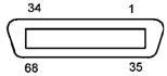
*1 : The optional I/O cable for the above connector consists of twisted pair wires--pairs of #1 and #35, #2 and #36, #34 and #68.
The reserved pins and output pins should be prevented from direct contact with other pins or conductive part. Direct contact could result in a controller failure or damage.
ID : 2604