
ID : 2605
Motion I/O Output Signals Pin Assignment
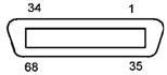
The following shows the pin assignment of motion I/O output signals for the safety motion specification controller.
View from the cable side |
|||||
| Terminal No. (*1) | Signal name | Wire color | Terminal No. (*1) | Signal name | Wire color |
|---|---|---|---|---|---|
| 1 | SLP 1, -1 (output) | Black | 35 | SLP 1, -2 (output) | Pink |
| 2 | Not connected | Brown | 36 | Not connected | Pink |
| 3 | RSM1 1, -1 (output) | Red | 37 | RSM1 1, -2 (output) | Pink |
| 4 | Not connected | Orange | 38 | Not connected | Pink |
| 5 | RSM2 1, -1 (output) | Yellow | 39 | RSM2 1, -2 (output) | Pink |
| 6 | Not connected | Black | 40 | Not connected | White |
| 7 | RSM3 1, -1 (output) | Brown | 41 | RSM3 1, -2 (output) | White |
| 8 | Not connected | Red | 42 | Not connected | White |
| 9 | RPM 1, -1 (output) | Orange | 43 | RPM 1, -2 (output) | White |
| 10 | Not connected | Yellow | 44 | Not connected | White |
| 11 | SOS 1, -1 (output) | Green | 45 | SOS 1, -2 (output) | White |
| 12 | Not connected | Blue | 46 | Not connected | White |
| 13 | Safe Reference Position Check 1, -1 (output) | Violet | 47 | Safe Reference Position Check 1, -2 (output) | White |
| 14 | Not connected | Gray | 48 | Not connected | White |
| 15 | SLP 2, -1 (output) | Pink | 49 | SLP 2, -2 (output) | White |
| 16 | Not connected | Black | 50 | Not connected | Gray |
| 17 | RSM1 2, -1 (output) | Black | 51 | RSM1 2, -2 (output) | Violet |
| 18 | Not connected | Brown | 52 | Not connected | Violet |
| 19 | RSM2 2, -1 (output) | Red | 53 | RSM2 2, -2 (output) | Violet |
| 20 | Not connected | Orange | 54 | Not connected | Violet |
| 21 | RSM3 2, -1 (output) | Yellow | 55 | RSM3 2, -2 (output) | Violet |
| 22 | Not connected | Green | 56 | Not connected | Violet |
| 23 | RPM 2, -1 (output) | Blue | 57 | RPM 2, -2 (output) | Violet |
| 24 | Not connected | Gray | 58 | Not connected | Violet |
| 25 | SOS 2, -1 (output) | Pink | 59 | SOS 2, -2 (output) | Violet |
| 26 | Not connected | Brown | 60 | Not connected | Gray |
| 27 | Safe Reference Position Check 2, -1 (output) | Red | 61 | Safe Reference Position Check 2, -2 (output) | Gray |
| 28 | Not connected | Orange | 62 | Not connected | Gray |
| 29 | Not connected | Yellow | 63 | Not connected | Gray |
| 30 | Not connected | Green | 64 | Not connected | Gray |
| 31 | Not connected | Blue | 65 | Not connected | Gray |
| 32 | DC power input +24V (when external power source is used) DC power output +24V (when internal power source is used) |
Pink | 66 | DC power input 0V (when external power source is used) DC power output 0V (when internal power source is used) |
Gray |
| 33 | Black | 67 | Blue | ||
| 34 | Brown | 68 | Blue | ||
*1 : The optional I/O cable for the above connector consists of twisted pair wires--pairs of #1 and #35, #2 and #36, #34 and #68.
*2 : If you change the Mini I/O power supply setting from the external power to internal power, the terminal No. 32 to 34 and No. 66 to 68 will be changed from the external DC power input to the internal DC power source output. For information about setting of Mini I/O power supply, refer to [Setting Method for Mini I/O Power Supply] of RC8 CONTROLLER MANUAL.
The reserved pins and output pins should be prevented from direct contact with other pins or conductive part. Direct contact could result in a controller failure or damage.
ID : 2605