
ID : 5796
Programming
This section describes the way of parameter setting and programing.
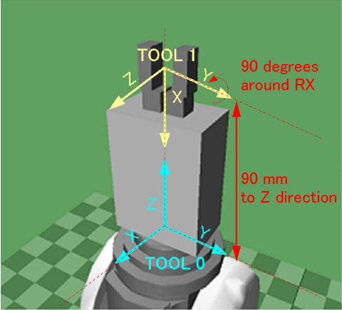
Tool coordinate
In this example, the end-effector has been offset to the Z direction of the tool coordinate by 90 mm.
The end-effector might be rotated around 90 degrees, depending on the status of the work unload position and the press-fitting position.
Tool1 coordinate : X=0 , Y=0 , Z=90 , RX=0 , RY=90 , RZ=0
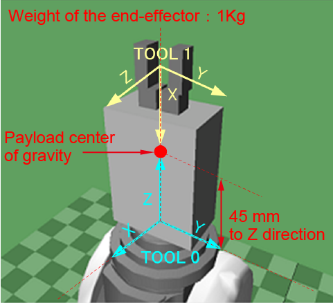
Internal load conditions
Compliance function requires the information about the mass and the center of gravity of the actual end-effector and workpieces.
- Mass of payload : 1kg(weight of the end-effector)
- Payload center of gravity : X = 0 mm, Y = 0 mm, Z = 45 mm
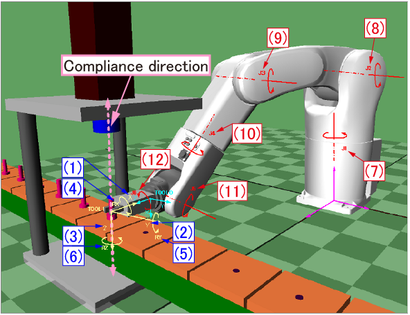
Descriptions for parameters
With the following robot model, this section describes parameters required for when TOOL1 gives under Z direction pressure.
| Coordinate-related parameters | |||
|---|---|---|---|
| No. | Tool coordinates | Control force | Position error allowance |
| (1) | X | 100[N] | 10[mm] |
| (2) | Y | 100[N] | 10[mm] |
| (3) | Z | 0[N] | 100[mm] |
| (4) | RX | 10[Nm] | 10[deg] |
| (5) | RY | 10[Nm] | 10[deg] |
| (6) | RZ | 10[Nm] | 10[deg] |
| Parameters for each axis | |||
|---|---|---|---|
| No. | Axis | Jiont current limit | Joint error allowance |
| (7) | 1-Axis | 100[%] | 50[deg] |
| (8) | 2-Axis | 0[%] | 100[deg] |
| (9) | 3-Axis | 0[%] | 100[deg] |
| (10) | 4-Axis | 100[%] | 50[deg] |
| (11) | 5-Axis | 0[%] | 100[deg] |
| (12) | 6-Axis | 100[%] | 50[deg] |
- Force and current limit values in the table are only reference.
- Specified values in the table above might be too flexible depending on the attitude, compliance direction and the weight of the end-effector. These values must be adjusted at the site.
- Damp and Spring must be adjusted at the site as well.
-
To achieve compliance as the target control force, the current limit value on the axis that affects the compliance direction needs to be 0%. However, doing so will deteriorate tracking performance to the robot motion and may degrade the smooth motion.
To achieve compliance as the intended control force, the target control force and current limit value should be adjusted at the actual site.
Coordinate-related parameters
| Control force (force) |
Required to control the robot. This value specifies the limit of force to be output. (Available range: 0 or larger) The smaller the value set here, the more likely the robot's motion will be affected by or follow the direction of less external force. In this example, the control force of Z direction is set to 0 so as to make it easy to give under the external force of Z direction. To enable the servo-lock for X and Y directions and RX RY and RZ rotation directions, set 100N to X and Y, and set 10Nm to RX, RY and RZ. |
|---|---|
| Position error allowance (PosEralw=allowable position deviation) |
Set the allowable servo deviation value for the arm end position. (Available range: 0 or larger) Setting this to larger value will reduce position-related error occurrence even if the deviation caused by the compliance motion increases. In this example, the position error allowance of Z is set to 100 mm; therefore the robot allows up to 100 mm of deviation for the Z direction as the compliance factor. The position error allowance settings, where X and Y directions are set to 10 mm and Rx, Ry and Rz rotation directions are set to 10 degrees, have been determined considering with the position allowances caused by the external force. |
Parameters for each axis
| Jiont current limit (CurLmt=current limit value) |
Set the torque values (electric current values) for motors of each axis. (Range: 0 to 100%) The nominal value is 100%. As this value reduces, the torque value (electric current value) reduces to gain springiness. In this example, the robot gives under the Z direction pressure of the tool coordinate; therefore, the larger loads are applied in the second, third and fifth axis than the first, fourth and sixth axis. Because of that, the Joint current limit are set to 0% for the second, third and fifth axis, and 100% for the first, fourth and sixth axis. |
|---|---|
| Joint error allowance (Eralw=allowable axis deviation) |
Set the allowable servo deviation value of each axis. (Available range: 0 or larger) When an external force is applied to the axis which current is limited, each joint rotates and the position-related errors will not be issued even if the deviation increases. In this example, the robot gives under the Z direction pressure of the tool coordinate; therefore, the larger loads are applied in the second, third and fifth axis than the first, fourth and sixth axis. Because of that, the Joint error allowance are set to 100 degrees for the second, third and fifth axis, and 50 degrees for the first, fourth and sixth axis. |
Teaching position
This example shows the teaching position of TOOL1
| P1 | Work unload position | X=200,Y=460,Z=220,RX=180,RY=0,RZ=-90,FIG=1 |
| P2 | Position before the press-fitting | X=390,Y=-200,Z=180,RX=180,RY=0,RZ=-180,FIG=1 |
| P3 | Press-fitting position | X=600,Y=-200,Z=105,RX=180,RY=0,RZ=-180,FIG=1 |
Programming Examples
Samp.pcs
Main program
#Include "CompOn.pcs"
#Include "CompOff.pcs"

Sub Main
 TakeArm

 '--- Internal load ---
 V1 = V(0,0,45)		'Enter the position of the center of gravity into V1
 PayLoad 1000 , V1	'Set the mass to 1000g,
 			'and the center of gravity at V1

 '--- TOOL1  ---
 P0 = P(0,0,90,0,90,0)	'Enter a value that you want to set in Tool1 into P0
 Tool 1, P0		'Set the value of P0 to Tool1
 ChangeTool 1		'Change Tool1

 '--- Work unloading ---
 Approach P,P1,@P 80
 Move L,@P P1

 'Grip a workpiece with the end-effector
 Depart L,@P 80

 '--- Move to the position before the press-fitting ---
 Move P,@P P2

 '--- Press-fitting position ---
 Approach P,P3,@P 70
 Move L,@P P3

 Call CompOn		'Enable the compliance function

 'Start Press-fitting machine
 'Press-fitting is under processing
 'Press-fitting is completed
 'Lifting up the press-fitting machine

 Call CompOFF		'Disable the compliance function

 'Release the workpiece from the end-effector
 Depart L,@P 70

 '--- Move to the position before the press-fitting ---
 Move P,@P P2

End Sub
CompOn.pcs
Enable the compliance function
Sub Main

 '--- Compliance parameter settings ---
 P11 = P(100, 100, 0, 10, 10, 10)	'Coordinates:
    					'Control-force setting values
 P12 = P(10,10,100,10,10,10)		'Coordinates:
    					'Position error allowance
					'setting values
 J11 = J(100,0,0,100,0,100)		'Each axis:
    					'Current limit setting values
 J12 = J(50,100,100,50,100,50)		'Each axis:
    					'Error allowance setting values

 ForceParam 1, 1, P11, PosEralw = P12, CurLmt = J11, Eralw = J12

 '--- Enable the compliance function ---
 ForceCtrl On, 1

End Sub
CompOff.pcs
Disable the compliance function
Sub Main

 '---Disable the compliance function ---
 ForceCtrl Off
End Sub
ID : 5796