
ID : 1983
System Configuration
A system configuration layout for the cooperative control function is as shown below.
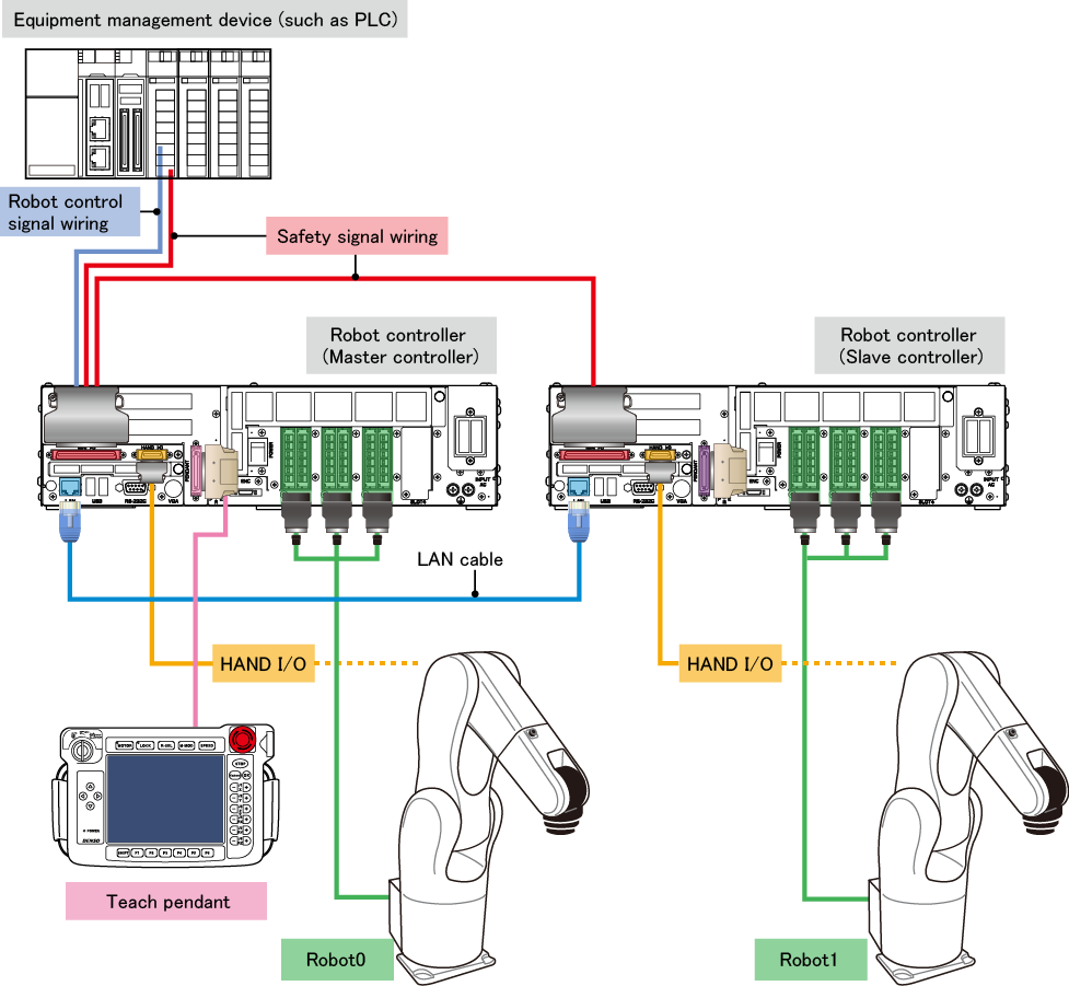
- Master controller
- Of robot controllers to control interlocked robots, one to which the equipment management device is connected through robot control signal wiring is called the master controller.
The master controller manages interlocked robot motions. Therefore, the equipment management device can operate multiple robots with them interlocked by sending robot instructions only to the master controller. - Slave controller
- Of robot controllers to control interlocked robots, ones other than the master controller are called slave controllers. The slave controller controls the robot (Robot1 in the figure above) according to the instruction from the master controller.
- Robot0, Robot1
- Robot names, such as "Robot0" and "Robot1", are assigned to interlocked robots.
A robot connected to the master controller Robot0 A robot connected to the slave controller Robot1 to Robot3
Robot names are also used to specify a control target robot in programs. - LAN cable
- A LAN cable is used to connect between robot controllers, which control interlocked robots. Information is communicated with each other through a LAN cable to interlock motions.
There are two communication methods: Ethernet only and Ethernet and EtherCAT.
To use Ethernet and EtherCAT, an EtherCAT master board and an EtherCAT slave board are optionally required, but this option allows higher accuracy robot interlocking. - Safety signals
- Of robot controller system I/O signals, safety-related ones, such as the Emergency Stop signal and Enable Auto signal, are called safety signals. These signals are used not to send instructions to the robot but stop the robot when it is near danger. For this reason, safety signals must be wired to all robot controllers.
- Robot control signals
- Of robot controller system I/O signals, non-safety signals are called robot control signals. These signals are used to send instructions to the robot and wired to the master controller only. In the figure above, the signals are wired to Mini I/O. However, with option boards (such as a DeviceNet slave board, CC-Link remote device board, and others), a field network can be used to send instructions to the robot.
- HAND I/O
- It is used to control a gripper or sensor connected to each robot. The slave controller HAND I/O is controlled by the master controller.
- Teach pendant
- It is connected to the master controller only. Even a robot connected to the slave controller can be operated by a teach pendant connected to the master controller.
Install a dummy connector to the slave controller. Without a dummy connector, a robot connected to the slave controller does not move. -
Mini pendant is not available for the cooperative control function.
For details about the connection method, refer to "System Design Procedure".
ID : 1983