ID : 3420
Precautions for Use
This section describes the precautions for use according to the following categories.
Note the following when using the robot protective jacket set for food processing:
- Precautions When Using the Robot Jacket
- Conditions for Designing the End-effectors
- Cleaning and Sterilizing the Robot Protective Jacket When the End-effector Is Removed
Precautions When Using the Robot Jacket
| Precaution | Detail | |||
|---|---|---|---|---|
|
Guide for replacement |
The robot jacket is expendable. It is recommended that it should be replaced after about one year of use. Also, check the robot jacket periodically and replace it if any scratch, tear, or fraying is found. * The robot jacket is warranted only during a period from taking it out of the package to putting it on the robot. |
|||
Notes on putting on/taking off |
|
|||
| Precautions for use |
|
|||
| Storage |
|
|||
| Others |
|
Conditions for Designing the End-effectors
Note the following when designing the end-effectors:
-
Maximum payload, maximum allowable inertia (inertia moment)
The following table shows the specifications of each robot with the protective jacket on.
Item VS-068 VS-087 Maximum payload 6 kg Maximum allowable inertia (inertia moment) Around J4 and J5: 0.440 kgm2
Around J6: 0.100 kgm2
Make sure to stay within the allowable ranges indicated above.
In calculation for an end-effector design, take into account not only an end-effector but also all loads to be applied to the flange such as workpieces, wiring, and piping. Design an end-effector (including workpieces) so that it does not vibrate.
When calculating the mass of the loads to be applied to the flange such as the end-effector and workpieces, add the mass (0.7 kg) of the robot mounting flange to the value.
For example, when the mass of the end-effector is 3.0 kg and the mass of any other object than the end-effector, such as workpieces, is 0.2 kg, the total mass of the load to be applied to the flange will be as follows:
3.0 kg + 0.2 kg + 0.7 kg = 3.9 kg If the end-effector design requirements are not met, the clamped sections of the robot unit may become loose, rattle or get out of position. In the worst case, the mechanical parts of the robot and the controller may become damaged.
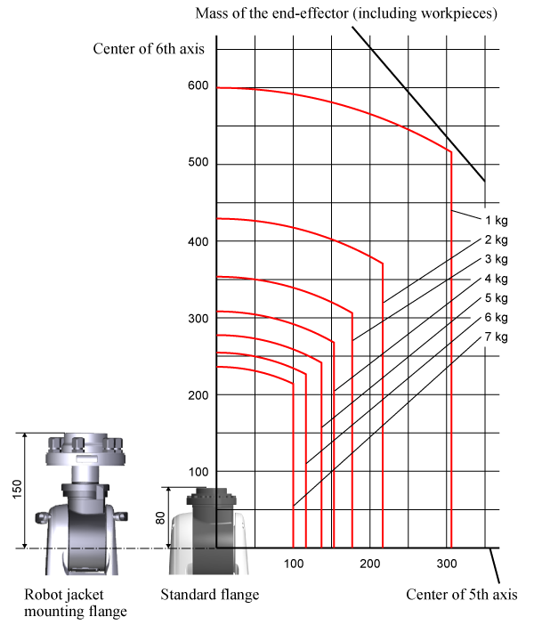
The graph below shows the distribution of the center of gravity position of an end-effector (including workpieces) whose volume is relatively small.
Referring to the graph, design an end-effector.

-
Position of the tool
Installing the robot jacket mounting flange moves the end-effector mounting face by 70 mm in the approach vector direction.
When setting the tool, add 70 mm to the approach vector direction.
-
Conditions for the end-effector mounting face (in an environment where water drops may fall near the end-effector)
The outer dimensions of the mounting face on the end-effector must have a diameter of 59 mm or more so that the circumference of the O-ring for the robot jacket mounting flange-A can be crushed.
Set the roughness of the contact surface with the O-ring on the end-effector to Rz 6.3 (Ra 1.6). Make sure that feed machining is not performed for the contact finish. If the conditions are not met, water drops may enter the robot jacket, causing damage to the robot unit.
-
If the diameter of the end-effector is larger than 70mm, when you lay the user wiring and piping through the cable gland, pay attention to the bending radius. In this case, because the end-effector is large, passing the user wiring and piping straight through the cable gland will hit the end effector. To by-pass the end-effector, the wiring and piping need to be bent.
If the bending radius of the wiring and piping are too small, it may be damaged or lead to loss of performance. To avoid that, ensure buffer space between the end-effector and the cable ground to provide sufficient bending radius to the user wiring and piping.
For details, refer to "Notes on End-effector Dimensions (PDF:215KB)".

Cleaning and Sterilizing the Robot Protective Jacket When the End-effector Is Removed
When washing and sterilizing the removed end-effector, be sure to attach the washing protective cover as shown in the figure below because liquid may enter the inside without the cover.
Make sure that the O-ring is installed on the robot jacket mounting flange-A before attaching the washing protective cover.
The washing protective cover is sold as an option (Part number: 410389-317*).

There are positioning holes for the washing protective cover on the contact surface with the robot jacket mounting flange-A. Attach the washing protective cover while aligning with the positioning holes on the robot jacket mounting flange-A.
- To wash the robot jacket when it is put on the robot, be sure to clean it with wiping.
- Do not use the washing protective cover for any other purpose than washing.

ID : 3420

