
ID : 2670
Example of Displaying Motor State (Using "Servo ON")
If you want to display the motor state (on/off) on the indicator light, the system function signal "Servo ON" can be used to display (For details about "Servo ON", click "here").
- Example of Circuit that Motor State Displays
- Installation Method of Indicator Light based on UL standard
Example of Circuit that Motor State Displays
The following drawings show examples of the circuit that motor state displays using "Servo ON".
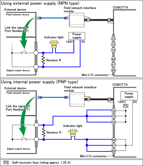
As shown in the figure above, the signal "Servo ON" (port number 771) of COBOTTA is output from the digital output device through the field network device of the external device.
For the signal of port number 771 received by the field network device, link it to the digital output device by a program of the external device.
"Resistor R" in the drawings above are to protect the circuit from rush current when the indicator light is lit. For details, refer to "here". However, please set the resistance value so as not to damage the circuit of the external device.
Installation Method of Indicator Light based on UL standard
If you install the indicator light based on UL standard, in addition above, be sure to observe the following items.
- The color of the indicator light should be yellow.
- Indicator light should be installed close to COBOTTA and it should be visible from anywhere.
-
If the indicator light is installed to a location subject to the effects of vibration that may adversely affect the life of the indicator light, the indicator light shall not be the following structure.
Screw-in type (It may loosen as a result of the effects of vibration.) Filament-type (It may cause premature filament failure as a result of the effects of vibration.)
ID : 2670