
ID : 7217
Connection Circuits for System Function Signals and User Signals
This section describes the circuit architecture used to connect the system function signals and user signals of Mini I/O to external devices (The table in "I/O Allocation" shows the system function signals and user signals with mark or
 mark).
The system function signals and user signals need a power supply for signals. Furthermore, COBOTTA provides two types of internal circuits to be used depending on the polarity of a voltage to be applied to signals.
The above information is explained in the following order:
- Connection circuits for input and output signals
- Voltage polarity (about NPN and PNP types)
- Use of internal power supply
- NPN and PNP-type I/O circuits and precautions on connection
- Display method of the motor state
Connection Circuits for Input and Output Signals
The schematic drawing of the Mini I/O input circuit is shown below.
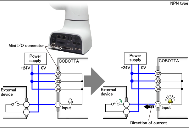
The numbers indicated on the Mini I/O connector shown above are the terminal numbers. Terminals No. 32 to 34 are the terminals for +24 V. Terminals No. 11 is an input signal. Inside COBOTTA, Terminals No. 32 to 34 and Terminals No. 11 are connected as shown above.
Closing the switch in an external device causes a current to run through the lamp in COBOTTA and causes it to light up. When the lamp lights up, COBOTTA recognizes that the switch in an external device is closed.
(Actually, switches and lamps are small elements embedded in products.)
Note that the use of an independent power supply as shown above is called the use of an "external power supply". The use of a power supply inside COBOTTA is called the use of the "internal power supply". The internal power supply is described later on this page.
In the factory default, an internal power source is selected. To use an external power source, perform necessary settings on COBOTTA. The power source setting is available from COBOTTA programming software. For information about how to set the power source, refer to "Display and Change of I/O Parameters".
The schematic drawing of the output circuit is shown below.
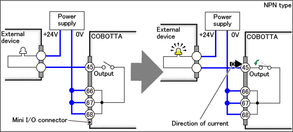
Terminals No. 66 to 68 of the Mini I/O connector are the terminals for 0 V. Terminals No. 45 is an output signal. The output circuit communicates the state of a switch in COBOTTA to an external device. Closing the switch in COBOTTA causes the lamp in the external device to light up. When the lamp lights up, the external device recognizes that the switch in COBOTTA is closed.
Such a connection method that uses power voltages to communicate signals is called "voltage input" for input signals and "voltage output" for output signals. All the system function signals and user signals are either voltage input or voltage output.
The above two figures show the circuit architectures of the "NPN type". For details on the "PNP type", refer to "Voltage Polarity (about NPN and PNP Types)" below.
Voltage Polarity (about NPN and PNP Types)
The schematic drawings of the input circuit and output circuit are shown below.
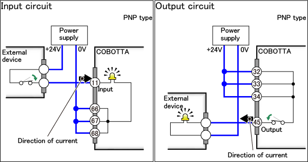
As shown in the above two figures, the "PNP type" is a circuit architecture in which voltages are applied to cause incoming currents for input signals and outgoing currents for output signals. The opposite type is called the "NPN type".
COBOTTA has two types of Mini I/O internal circuit; "PNP type" and "NPN type". Select one of the types when you place an order.
The type that should be selected depends on an external device to be connected. Select the same type as the type of an external device.
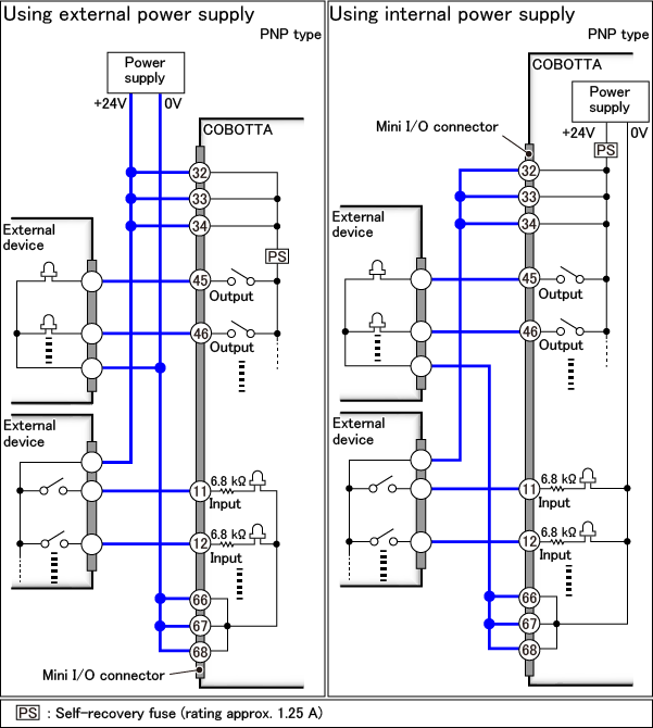
Use of Internal Power Supply
The internal power supply of COBOTTA can be used as a power supply for signals.
The schematic drawings of the input circuit and output circuit to use the internal power supply are shown below.
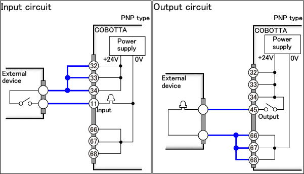
The maximum allowable current of the internal power supply is 1.3 A. If the total sum of currents that run through the signal lines exceeds 1.3 A, use an external power supply that can provide a larger current than it.
The above figure shows a PNP-type circuit architecture. For details on the circuit architecture of "NPN type," refer to "Precautions on NPN and PNP-type I/O Circuits and Connection" below.
NPN and PNP-type I/O Circuits and Precautions on Connection
NPN-type I/O Circuit

PNP-type I/O Circuit
Precautions on Connection
- The lines in blue in the above circuit are connected with the Mini I/O cable (option).
- In actuality, the COBOTTA internal circuit has a self-recovery fuse as shown in the above circuit. A self-recovery fuse is an element that prevents overcurrent from running through a circuit. If a larger current than the rated value of the self-recovery fuse runs due to an error in wiring or a short-circuit between wiring, the temperature of the self-recovery fuse becomes higher, allowing only a minute current to run. If this occurs, first turn off the power of COBOTTA and the devices connected to COBOTTA. Then, eliminate the cause of overcurrent and wait until the temperature of the self-recovery fuse becomes lower before turning on the power of the devices.
- A current-limiting resistor is connected to the input signal (shown in the above circuit).
- Use a proximity switch with a leakage current of 1 mA or less if it is to be connected to the input signal.
-
Do not connect the +24 V terminals (Terminals No. 32 to 34) to ground when the internal power supply is used.
COBOTTA may be damaged if the +24 V terminals are connected to ground.
- The maximum allowable current of the output signal is 70mA. The consumption current of the devices to be connected such as PLC and relay coils must be lower than the allowable current.
-
The induction load such as a relay coil on the output signal must be a type with a built-in diode (for absorbing a counter electromotive force). To use a type without a built-in diode, install a diode 1S1888 (Toshiba) or equivalent in proximity to the coil, etc.
Connect an external diode, if needed, while paying attention to the polarities of the diode. The output circuit may be damaged if the polarities are incorrect.
-
To connect a lamp to the output signal, use a lamp with rating of 0.5 W or less to configure a circuit in which a minute current ("dark current") runs through the lamp even if the output signal is turned off (the internal switch is open).
The figure below shows an example of a circuit in which a dark current runs. Set the resistance value of resistor R so that a current not larger than 1/3 of the lamp's rated current runs when the output signal is turned off (the internal switch is open).
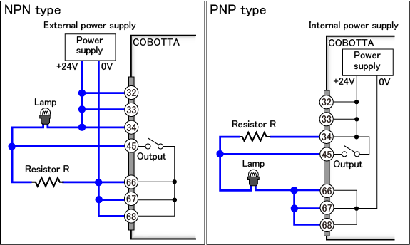
The lamp has a small initial resistance. Unless a dark current runs through it, a large current ("rush current") runs when it is turned on. If a rush current runs, the output circuit may be damaged.
- After power-on of COBOTTA, until the software startup processing is completed, do not apply voltage to input signals nor use the output signals.
Common Precautions for "Safety Signals", "System Function Signals" and "User Signals"
The following precautions are indicated for not only system function signals and user signals but also safety signals.
- Correctly apply the specified voltage (24V±10%) to the input terminals. If you connect to a power supply which is out of specification, the provided function can not expect its full capacity or performance. Doing so may decline the safety function, and the product itself may break or burn as a result.
- Wire the Mini I/O cable far from high-voltage line or power lines.
- Avoid bending or pulling down the Mini I/O cable excessively. Excessively bending and/or pulling down will result in broken lead wires.
- Be sure to turn off the power supply before wiring.
-
When using the external power source to Mini I/O, if you turn on the power to the COBOTTA without supplying the external power, or supply the external power after that of the COBOTTA, an error may occur and fail to operate the COBOTTA as a result.
Be sure to supply the external power before the COBOTTA will be powered on.
Display Method of the Motor State
If you want to display the motor state (on/off) on the indicator light, the system function signal can be used to display.
If Field network interface module for COBOTTA option is not used, the system function signal "Operation preparation completed" is used.
If Field network interface module for COBOTTA option is used, the system function signal "Servo ON" is used.
For details, refer to the following links.
ID : 7217