
ID : 7262
Connection Circuit for Safety Signals
This section describes the connection circuit for safety signals (The table in "I/O Allocation" shows the safety signals with mark).
The safety signals are explained in the following order:
- Connection Circuits for External Emergency Stop Input and Protective Stop Input
- Connection Circuit for STO Monitor Output
- Connection Circuit for Emergency Stop Box Status Output
- How to Use Dummy Connector (I/O)
- Items to Note Other Than Above
Connection Circuits for External Emergency Stop Input and Protective Stop Input
The external emergency stop input and the protective stop input are signals used to stop COBOTTA in emergency. For details, refer to "Signals for Safety Use."
The figure below shows a schematic drawing of a connection circuit for the external emergency stop input.
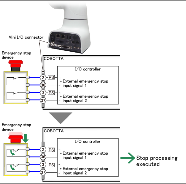
The numbers indicated on the Mini I/O connector shown above are the terminal numbers. There are two lines for external emergency stop input: Terminals No. 2 and 36 for the first line and Terminals No. 3 and 37 for the second line.
COBOTTA can move if Terminals No. 2 and 36 are connected ("short-circuited") and also Terminals No. 3 and 37 are short-circuited. COBOTTA stops if either of the pairs is not connected ("open").
Therefore, an emergency stop device to be connected to external emergency stop input must be a type whose two switches ("contacts") are open when the button is pressed. Do not use semiconductor contacts such as transistors and FETs but mechanical contacts ("having contacts").
There are also two lines for protective stop input. Two lines are provided because a safe state can be maintained even if one of them malfunctions due to a failure of contact. This is explained below using an example of the connection circuit for the protective stop input.
The figure below shows a schematic drawing of a connection circuit for the protective stop input.
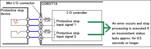
There are two lines for protective stop input: Terminals No.4 and 38 for the first line and Terminals No.5 and 39 for the second line. COBOTTA stops if one of the lines is open in the same way as for external emergency stop input.
Suppose that, if you want to open both the contacts of the protective stop device, one of them fails and cannot be open. COBOTTA is designed to stop if inconsistency between the states of the two lines continues approximately for 0.5 seconds (This is also the same for external emergency stop input). Even if one of the contacts of the protective stop device fails, therefore, COBOTTA stops and enters a safe state.
Precautions on External Emergency Stop Input and Protective Stop Input
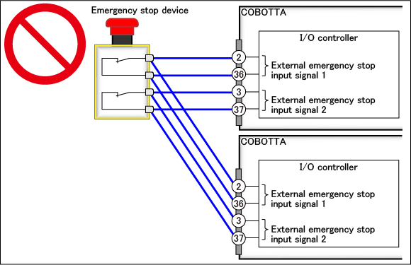
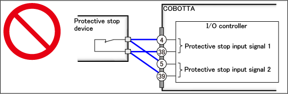
COBOTTA may fail if multiple signals are connected to any of the contacts of the emergency stop device and the protective stop device as shown below. This is strictly prohibited.
- Connection to multiple COBOTTA units (The same applies to protective stop devices).
-
- Connection to one COBOTTA unit (The same applies to emergency stop devices).
-
Connection Circuit for STO Monitor Output
The STO monitor output is a signal used to inform to an external device that it is certain COBOTTA is unable to move. For details, refer to "STO Monitor Output".
The STO monitor output has a circuit architecture of using the power. The figure below shows a schematic drawing of a connection circuit for the STO monitor output.
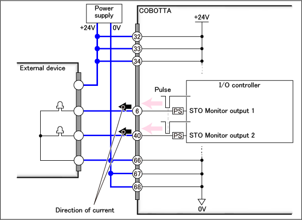
There are also two lines for the STO monitor output: Terminal No. 6 for the first line and Terminal No. 40 for the second line. When COBOTTA may be able to move, +24V is being applied to both the two lines ("ON" condition). When it is certain COBOTTA is unable to move, both the two lines have 0V ("OFF" condition).
However, when the lines are ON, they are periodically turned OFF. The figure below shows when the lines are turned OFF.
The lines are turned OFF three times for a period of 750 µs at 8 ms intervals, and then the same waveform is output again after 8 hours.
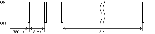
This is intended to inform to an external device that the STO monitor output is correctly running.
To make sure that the STO monitor output is correctly running, check that the states of the two lines are the same. For example, when the first line is ON and the second line is OFF, the STO monitor output may not be correctly running. In such a case, take measures to maintain the entire equipment in a safe state.
The STO monitor output has a PNP-type circuit architecture, regardless of the internal circuit types of COBOTTA. Connect with PNP-type circuit architecture even if the internal circuit of your COBOTTA is NPN-type.
Connection Circuit for Emergency Stop Box Status Output
The emergency stop box status output is a signal used to inform the status of the emergency stop box to an external device. For details, refer to "Signals for Safety Use."
The figure below shows a schematic drawing of a connection circuit for the external emergency stop box status output.
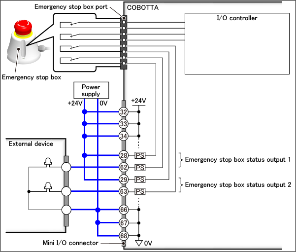
The emergency stop box has four contacts in it. All the contacts are opened when you press the push-button switch in the emergency stop box. Two of these contacts are connected to the Mini I/O connector. Therefore, there are also two lines for the emergency stop box status output.
The emergency stop box status output is directly connected to the Mini I/O connector without going through the internal circuit of COBOTTA. Therefore, an external device can recognize the emergency stop box status even if the COBOTTA power is not turned ON.
A power supply is used for connection with an external device. The above circuit is a PNP-type circuit architecture. It can be changed to an NPN-type circuit architecture depending on the connection method.
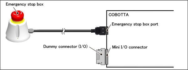
How to Use Dummy Connector (I/O)
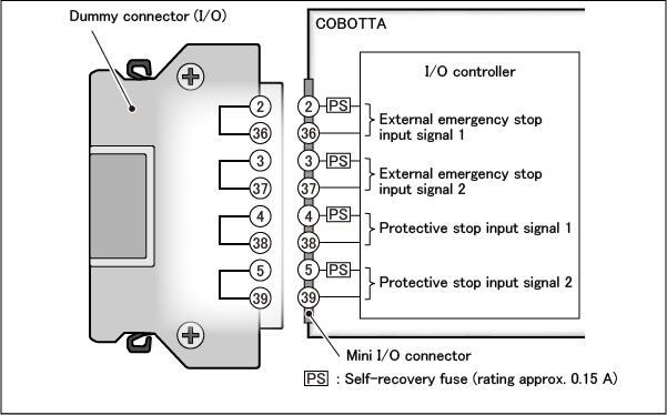
In the dummy connector (I/O), the external emergency stop input and protective stop input signals are short-circuited as shown below. Use the dummy connector when you choose not to use any of the Mini I/O signals to use COBOTTA.
However, use the dummy connector only after conducting thorough risk assessment on using COBOTTA and making sure that it is safe without using any of the Mini I/O signals (particularly safety signals such as the external emergency stop input).
To make COBOTTA ready for operation using the dummy connector (I/O), you need to insert it into the Mini I/O connector of COBOTTA and also do as follows:
- Insert the emergency stop box into the emergency stop box connector and release the push button of the emergency stop box.
- Set the power supply of Mini I/O as the internal power supply. (For details on the setting, refer to "Display and Change of I/O Parameters".
Items to Note Other Than Above
The following shows items to note other than the description provided above:
- Incorrect wiring may damage the safety function. Be sure to set all the wiring correctly, and check it before operating.
- Configure the safety system by using the both wirings of Line 1 and Line 2. Configuring with only one Line for the safety system may damage the safety function.
-
If you set the device of human body detection, such as light curtains, etc., be sure to the matters as follows:
Set the device of human body detection back further from the minimum distances in order to detect hazards; so the COBOTTA is able to stop before the human body reach the hazard zones. This is according to Safety Distance Calculation (ISO 13855, etc.,).
For Safety Distance Calculation, consider the stopping distance may differ depending on the movement speed of the COBOTTA.
If the approach to the detection device of the human body is not defined and the safety distance is out of range to the human body detection, the security cannot be guaranteed.
Set up for safety measures, such as safety fences.
Common Precautions for "System Function Signals", "User Signals" and "Safety Signals"
The following precautions are indicated for not only safety signals but also system function signals and user signals.
- Correctly apply the specified voltage (24V±10%) to the input terminals. If you connect to a power supply which is out of specification, the provided function can not expect its full capacity or performance. Doing so may decline the safety function, and the product itself may break or burn as a result.
- Wire the Mini I/O cable far from high-voltage line or power lines.
- Avoid bending or pulling down the Mini I/O cable excessively. Excessively bending and/or pulling down will result in broken lead wires.
- Be sure to turn off the power supply before wiring.
-
When using the external power source to Mini I/O, if you turn on the power to the COBOTTA without supplying the external power, or supply the external power after that of the COBOTTA, an error may occur and fail to operate the COBOTTA as a result.
Be sure to supply the external power before the COBOTTA will be powered ON.
ID : 7262