
ID : 7498
System Configuration Diagram
The COBOTTA system configuration diagram is shown below.
Brief descriptions of each device are provided below the diagram.
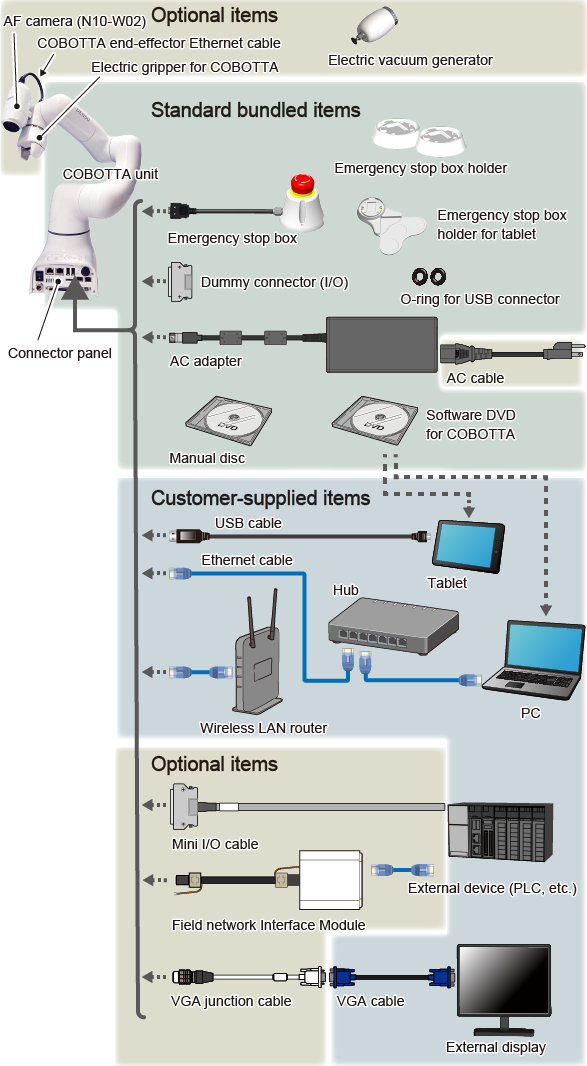
Standard Packed Items
- COBOTTA unit
-
A robot that will operate according to the robot program created by the customer.
- Emergency stop box
-
The switch to stop COBOTTA.
- Emergency stop box holder
-
The holder to fasten an emergency box.
- Emergency stop box holder for tablet
-
The holder to fasten an emergency box to a tablet.
- Dummy connector (I/O)
-
Use this connector when the optional Mini I/O cable is not used.
- O-rings for USB connectors
-
These are used when connecting the USB connector to COBOTTA.
- AC adapter
-
The adapter used to supply electricity to COBOTTA.
AC cable is an optional item. Select the cable appropriate for the country where COBOTTA is used.
- Manual disk
-
User's manual for COBOTTA.
- COBOTTA software DVD
-
The software used to operate COBOTTA and create robot programs.
Install the software on the tablet or PC.
The Android OS app can be downloaded from "Google Play".
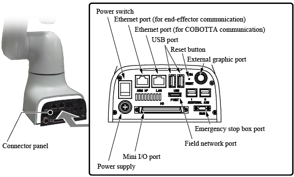
- Connector panel
-
All connectors used to connect each device to the COBOTTA unit are provided here.
The (power) switch to startup the COBOTTA system is also located here.
For the location of each connector, refer to the figure below.
Options
- AF camera (N10-W02)
-
Use the camera to identify positions and shapes of objects with COBOTTA.
- COBOTTA end-effector Ethernet cable
-
This cable is used to connect the AF camera (N10-W02) with the Ethernet port (for end-effector communication) on the connector panel.
- Electric gripper for COBOTTA
-
Use the gripper to pick up and move objects with COBOTTA.
- Electric vacuum generator
-
Use this vacuum generator to apply vacuum on an object and move it objects with COBOTTA.
- AC cable
-
Select the AC cable according to the outlet type appropriate for the country where COBOTTA is used.
- Mini I/O cable
-
This cable is used to connect the external device (PLC) to COBOTTA.
- Field network interface module
-
Use this module to connect an external device (PLC) with COBOTTA over field networks (PROFINET, EtherNet/IP, EtherCAT).
- VGA junction cable
-
This is used to display the COBOTTA development screen for the OSS version.
Items Prepared by Customer
- Tablet
-
This is used to operate COBOTTA and create robot programs
(a PC can be used to perform the same tasks. A tablet is not required if a PC is used).
COBOTTA software must be installed.
The tablet OS must be Android or Windows.
Tablet size 8 inches or larger is recommended.
- USB cable
-
When a tablet is used, connect the tablet and COBOTTA unit using a USB cable or wireless LAN router (wireless connection). When using the USB cable, be sure to use a Type-A connector on the COBOTTA side.
- PC
-
This is used to operate COBOTTA and create robot programs
(a tablet can be used to perform the same tasks. PC is not required if a tablet is used).
COBOTTA software must be installed.
The PC OS must be Windows.
- Ethernet cable
- When a PC is used, connect the PC and COBOTTA unit using an Ethernet cable.
- Hub
-
This is used to connect multiple Ethernet devices to the COBOTTA unit.
When using the optional AF camera, a Hub or PoE injector with a PoE power feed function is required.
- Wireless LAN router
-
This is required to connect to COBOTTA via wireless communication when using a tablet.
- External device (PLC, etc.)
-
COBOTTA's robot programs can be executed and stopped from external devices (PLC, etc.).
The motion of COBOTTA can also be stopped from an external device.
- VGA cable
-
This is used to display the COBOTTA development screen for the OSS version.
- External display
-
This is used to display the COBOTTA development screen for the OSS version.
ID : 7498