
ID : 2841
Safety Signal Wiring for the RC8A Standard Specification
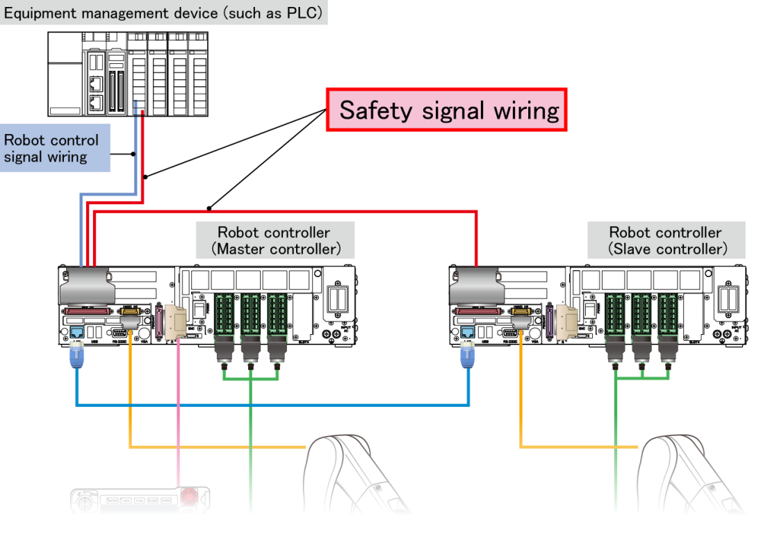
The flowing describes how to wire safety signals when a robot controller has the RC8A Standard specification.
This applies to an area indicating "Safety signal wiring" in the entire system shown below.
Safety Signals to Be Connected
Connect the following signals (all are Mini I/O signals) to both the master and slave controllers.
- External Emergency Stop input
- Protective Stop input
- Enable Auto input
For the master controller, the above signals should be connected from the equipment management device.
Of output signals on the master controller, ones interlocked with the above input signals can be used for the slave controller. For example, when the Enable Auto input is turned ON, the Auto Mode Mutual Monitoring (output) is turned ON accordingly (The teach pendant or mini pendant mode switch needs to be set to "AUTO"). Therefore, the Auto Mode Mutual Monitoring (output) on the master controller can be used as the Enable Auto input signal on the slave controller.
However, the Protective Stop input on the slave controller must be short-circuited.
Of Mini I/O signals on the slave controller, the following signals are inactive.
Do not wire them.
| Signal | Terminal No. |
|---|---|
System I/O signals However, the following signals are excluded.
|
No. 11 to No. 26 and No. 46 to No. 60 |
| User I/O signals |
Safety Signal Wiring Example
When two robots are linked for cooperation, the signal wiring may be simple because the safety signal on the master controller can be directly connected to the slave controller.(Relays are used for some contacts.)
On the other hand, if three or more robots are linked for cooperation, the safety signal of the master controller needs to be distributed to each slave controller with relays.
For about wiring example, refer to the following links.
- Sample wiring diagram for two robots (PDF:190KB)
- Sample wiring diagram for three or more robots (PDF:164KB)
The same wiring can be used even if the slave controller is RC8.
The wiring can be connected to Mini I/O using "I/O cable for Mini I/O" or "Mini I/O connector kit" (both are optional).
Mini I/O connector kit consists of a connector only. Customers need to prepare cables by themselves when selecting this part though, there is also advantage that the master controller's Mini I/O wiring can be easily separated into two devices (an equipment control device and the slave controller).
For the option part numbers and connector pin arrangement, refer to the tables below.
- Option part numbers
-
Part name Part number I/O cable for "Mini I/O" (68 pins) 8 m 410141-270* 15 m 410141-271* Mini I/O connector kit 410159-019*
- Connector pin arrangement
-
Mini I/O type I/O allocation mode Reference NPN Mini I/O dedicated Refer to "[NPN type, Mini I/O dedicated mode] Mini I/O Pin Assignment for RC8A". Other than Mini I/O dedicated Refer to "[NPN type, other than Mini I/O dedicated mode] Mini I/O Pin Assignment for RC8A". PNP Mini I/O dedicated Refer to "[PNP type, Mini I/O dedicated mode] Mini I/O Pin Assignment for RC8A". Other than Mini I/O dedicated Refer to "[PNP type, other than Mini I/O dedicated mode] Mini I/O Pin Assignment for RC8A".
ID : 2841