
ID : 5468
Sensor Setting
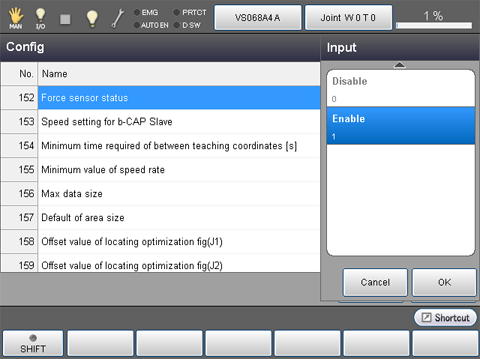
Enabling the Force Sensor
From the top screen, press [F2 Arm] - [F6 Aux] - [F1 Config]
In the [Config] window, click [152 Force sensor status], and then click [Enable] - [OK].
Setting the Sensor Type
From the top screen, press [F2 Arm] - [F2 Force Control] - [F5 Sensor] - [F1 Sensor Setting]
Set the sensor type you use.
For details, refer to the following table.
| No. | Item name | Parameter | Description |
|---|---|---|---|
| 1317 | Force sensor type |
0: WACOH |
Select when you use a WACOH-TECH force sensor. |
|
1: ATI |
Select when you use a ATI Industrial Automation force sensor. |
||
|
2: SINTOKOGIO |
Select when you use a SINTOKOGIO force sensor. |
According to the sensor type, default values of the parameters in the following table will change.
| Force sensor type | Parameter to be changed | ||
|---|---|---|---|
| No. | Item name | Default | |
| 0: WACOH | 1115 | port number | 5001 |
| 1314 | Connecting mode | 0 (TCP) | |
| 1: ATI | 1115 | port number | 49152 |
| 1314 | Connecting mode | 1 (UDP) | |
| 2: SINTOKOGIO | 1115 | port number | 10001 |
Hardware Setting
From the top screen, press [F2 Arm] - [F2 Force Control] - [F5 Sensor] - [F1 Sensor Setting]
Perform the hardware settings. Parameters to be set are different depending on the sensor type. For details, refer to the following information.
In the force sensor-based force control function, the error "Force limit over in force control 0x8320152F" occurs when the force and moment detected by the sensor exceed the limits.
The limit values are the "Force sensor force limit" and "Force sensor moment limit"
WACOH-TECH Force Sensor
When you purchase a force sensor of WACOH-TECH Inc., a data sheet is shipped with the product. Enter the setting values written in the sheet.
| No. | Item name | Units |
|---|---|---|
| 1116 | Force corresponding value (X) | pulse/N |
| 1117 | Force corresponding value (Y) | pulse/N |
| 1118 | Force corresponding value (Z) | pulse/N |
| 1119 | Moment corresponding value (RX) | pulse/Nm |
| 1120 | Moment corresponding value (RY) | pulse/Nm |
| 1121 | Moment corresponding value (RZ) | pulse/Nm |
| 1122 | Force sensor force limit | N |
| 1123 | Force sensor moment limit | Nm |
ATI Industrial Automation Force Sensor
For the force sensor of ATI Industrial Automation, enter the following values.
| No. | Item name | Units | Setting value |
|---|---|---|---|
| 1116 | Force corresponding value (X) | pulse/N | 1000000 |
| 1117 | Force corresponding value (Y) | pulse/N | 1000000 |
| 1118 | Force corresponding value (Z) | pulse/N | 1000000 |
| 1119 | Moment corresponding value (RX) | pulse/Nm | 1000000 |
| 1120 | Moment corresponding value (RY) | pulse/Nm | 1000000 |
| 1121 | Moment corresponding value (RZ) | pulse/Nm | 1000000 |
SINTOKOGIO Force Sensor
For the force sensor of SINTOKOGIO,LTD, substitute the conversion formula of the following table in the rated values of sensor you use. Enter the calculation result values.
| No. | Item name | Units | Setting value (conversion formula) |
|---|---|---|---|
| 1116 | Force corresponding value (X) | pulse/N | 10000 / rated value of the transitional force Fx (absolute value) [N] |
| 1117 | Force corresponding value (Y) | pulse/N | 10000 / rated value of the transitional force Fy (absolute value) [N] |
| 1118 | Force corresponding value (Z) | pulse/N | 10000 / rated value of the transitional force Fz (absolute value) [N] |
| 1119 | Moment corresponding value (RX) | pulse/Nm | 10000 / rated value of moment Mx (absolute value) [Nm] |
| 1120 | Moment corresponding value (RY) | pulse/Nm | 10000 / rated value of moment My (absolute value) [Nm] |
| 1121 | Moment corresponding value (RZ) | pulse/Nm | 10000 / rated value of moment Mz (absolute value) [Nm] |
For information about rated values of force sensor, refer to "Available force sensor".
For example, to use a standard model force sensor, values will be the following.
Force corresponding value(X) = 10000 / 500 = 20 Force corresponding value(Y) = 10000 / 500 = 20 Force corresponding value(Z) = 10000 / 500 = 20 Moment corresponding value(RX) = 10000 / 20 = 500Moment corresponding value(RY) = 10000 / 20 = 500Moment corresponding value(RZ) = 10000 / 20 = 500
Installation Position And The Payload Condition Setting
From the top screen, press [F2 Arm] - [F2 Force Control] - [F5 Sensor] - [F1 Sensor Setting]
For details, see the table below.
Setting of the Installation Position
| No. | Item name | Units |
|---|---|---|
| 1034 | Attachment position (X) | mm |
| 1035 | Attachment position (Y) | mm |
| 1036 | Attachment position (Z) | mm |
| 1037 | Attachment position (RX) | deg |
| 1038 | Attachment position (RY) | deg |
| 1039 | Attachment position (RZ) | deg |
Specify a desired installation position with the use condition parameter. Setting value is arbitrary.
about the force sensor coordinate system, see "Force sensor coordinate system" written below.
Force Sensor Coordinate System
A force sensor coordinate system is a coordinate system defining the detection force of the force sensor or the direction of moment.
As shown below, the installation position is defined with the coordinate center of the force sensor and the direction of the coordinate axes (viewed from the TOOL0 coordinate system) in tool definition.
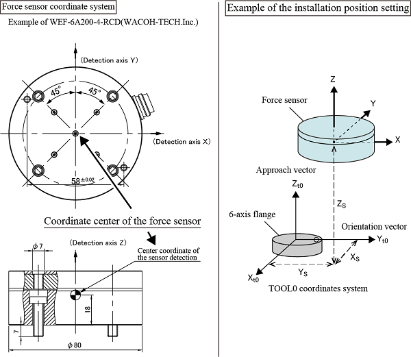
In "Example of the installation position setting" shown in the image above, the coordinate center of the force sensor is TOOL0 coordinate(Xs, Ys, Zs), and the direction of the coordinate axis is the direction which rotates 90 degrees around the Z-axis of the TOOL0 coordinate system. Based on that, enter (Xs, Ys, Zs, 0, 0, 90) for the installation position setting.
The coordinate center of force sensor is written in the outer drawing of each force sensor.
For the force sensor of SINTOKOGIO,LTD., the coordinate center of the force sensor is "sensor focus point".
For the force sensor of ATI Industrial Automation, the coordinate center of the force sensor is "Sensing Reference Frame Origin".
Payload Condition Setting
| No. | Item name | Units |
|---|---|---|
| 1297 | Force sensor Mass of payload | g |
| 1298 | Force sensor Payload center of gravity X | mm |
| 1299 | Force sensor Payload center of gravity Y | mm |
| 1300 | Force sensor Payload center of gravity Z | mm |
| 1301 | Force sensor Payload moment of inertia Ix | kgcm² |
| 1302 | Force sensor Payload moment of inertia Iy | kgcm² |
| 1303 | Force sensor Payload moment of inertia Iz | kgcm² |
Set the mass of load, the center of gravity, and the inertia through the center of gravity on the tip of the force sensor.
(e.g.) If the tip of the force sensor equips a gripper, set the total value of the gripper-mounting stay and the gripper to each component.
For about the position of the payload center of gravity on the tip of the sensor, refer to the figure below.
Position of the payload center of gravity
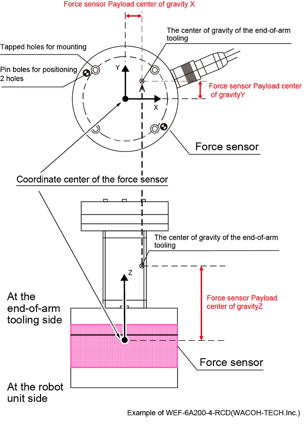
Set the Mass of payload and the center of gravity precisely. Incorrect setting may fail to compensate the center of gravity. As a result, the robot may perform abnormally when the force sensor–based force control function is performed.
Setting of the Sensor Maximum Limit Check Function
When the robot moves with the force control, the force sensor controls in order that the applied force does not exceed its maximum rated value. However, when the robot moves without the force control, it can move at high speed without checking sensor's maximum rated value; this may damage the sensor.
The sensor maximum limit check function protects the sensor from such robot's high speed motion. Once a robot speed exceeds the specified maximum limit, an error occurs.
For about the setting, refer to the following table.
This function is available from Ver.1.8.* or higher.
| No. | Item name | Units | Description |
|---|---|---|---|
| 1310 | Force sensor force limit | N | Set the maximum force [N] for the sensor maximum limit check function |
| 1311 | Force sensor moment limit | Nm | Set the maximum moment [Nm] for the sensor maximum limit check function |
| 1312 | Force sensor limit check | - | Enable/Disable the sensor maximum limit check function |
All the settings for the sensor maximum limit check function must be done always. Otherwise, the sensor may be damaged.
Communication Setting with the Force Sensor
Perform the communication settings of the robot controller to communicate with a force sensor. The way of setting differs depending on the communication standard used for the force sensor. For details, refer to the following description.
For RS-422A Communication
To establish a communication using RS-422A, set the parameters shown in the table below.
| No. | Item name | Description |
|---|---|---|
| 1314 | Connecting mode | Set the connection method when connecting to the sensor. Set to "2: RS422". |
| 1316 | Client Port number | Set the client port number of the sensor. Enter the COM number of RS-422A which has been selected by "Enabling a FIFO Buffer" in "RS-422A Communication Board Setting". |
This function is available Ver.2.2.* or higher.
For Ethernet Communication
For Ethernet communication, enter the parameters shown in the following table, and enter the force sensor IP address.
| No. | Item name | Description |
|---|---|---|
| 1314 | Connecting mode | Set the connection method when connecting to the sensor. For the force sensor of ATI Industrial Automation, select [1: UDP]. |
For information about how to enter an IP address of force sensor, click here.
Checking the Force Sensor
After mounting the force sensor, check that each setting are configured as intended by using "Sensor value" which is described in the "Monitoring Function of the Force Sensor Values".
If the force sensor is connected to other sensor with incorrect IP address setting, or is connected to wrong position, the force sensor works toward wrong direction; it may damage the tools and workpieces.
Resetting of the Force Sensor
When you need to reset the force sensor, that is available by using a teach pendant or a command.
Teach Pendant
Reset the force sensor by using Sensor Calibration. For details, refer to "Sensor Setting of Force Control".
Command
When ForceSensor is specified with "0" , the force sensor shall be reset. For details, refer to ForceSensor.
ID : 5468
- Related Information
- Entering IP Address of Force Sensor