
ID : 2272
Traveling Shaft
To link the robot with an extended-joint, create a traveling shaft with Related axis setting of WINCAPSIII.
How to Create a Traveling Shaft Model
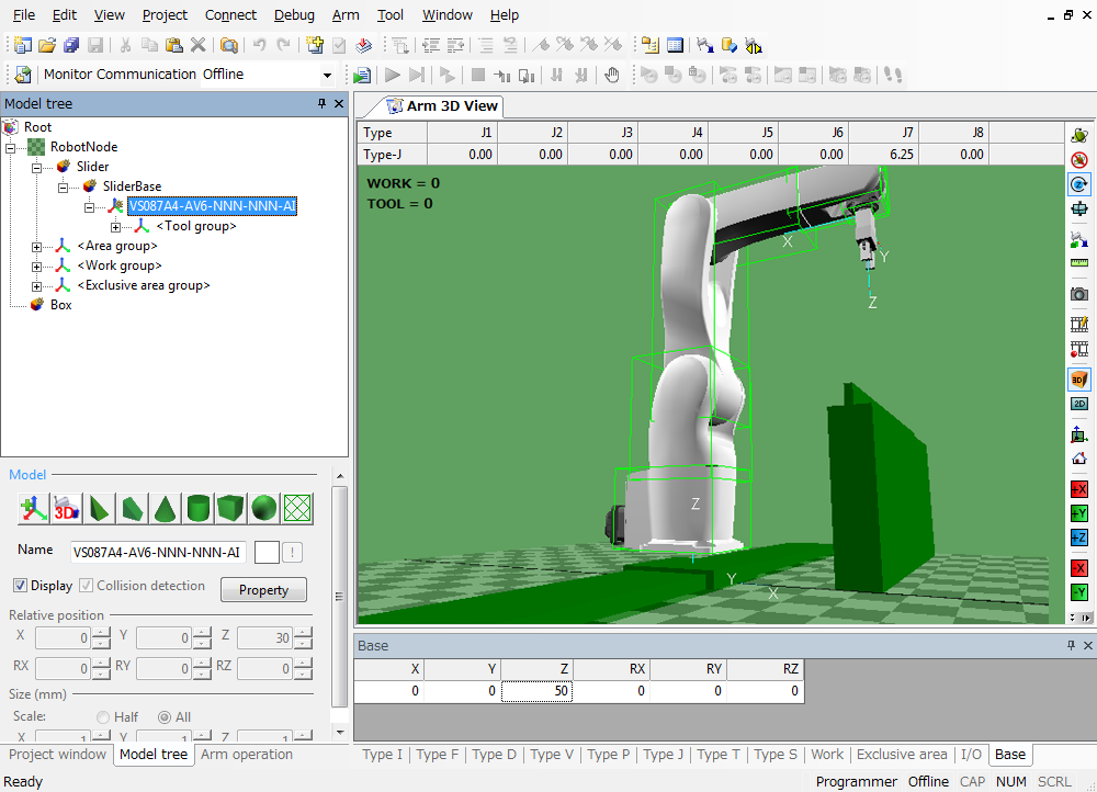
In the Arm modeling pane, create an object between RobotNode and a robot model (in this example, VS087A4-AV6-NNN-NNN-AI), and then configure the new object so that it behaves as an extended-joint.
In this sample, add a Slider object first, add a SliderBase object to below the Slider object, and then place the robot on the SliderBase object.
- Enable necessary axes from [Joint motion] in [Joint Setting Table].
- Enable [190:BASE number setting] in [User] parameter.
1
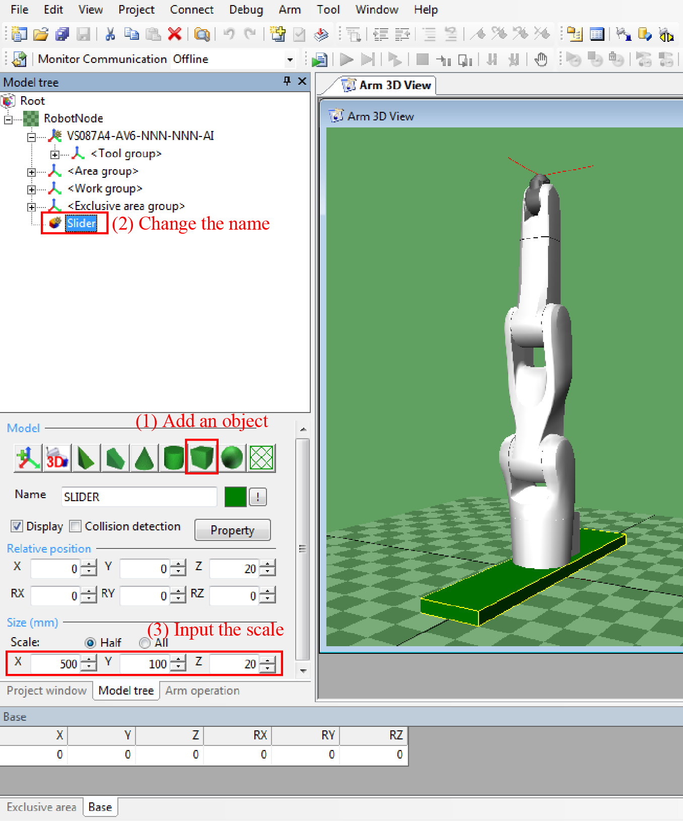
Select RobotNode, add an object, and then rename it Slider.
2
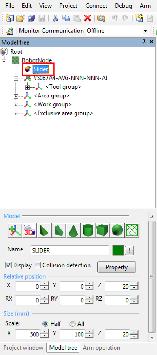
Move the Slider object to the position between RobotNode and robot model.
3
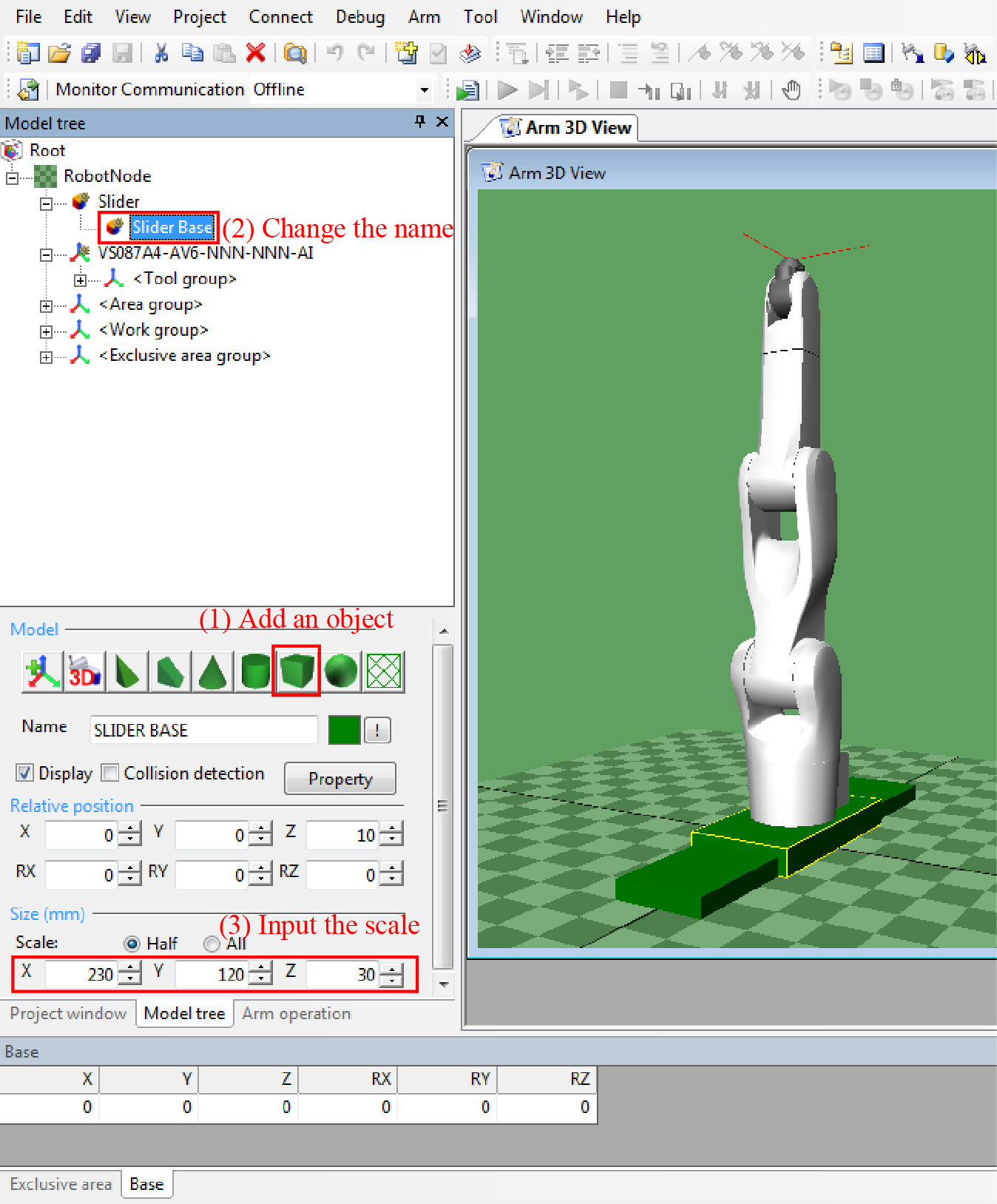
Add an object to below the Slider model, and then rename it SliderBase.
4
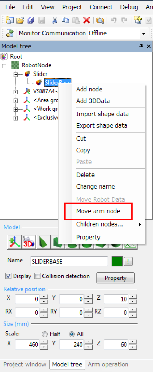
Right-click the SliderBase object to display the command list.
Press [Move arm node] to move the robot model to below the SliderBase.
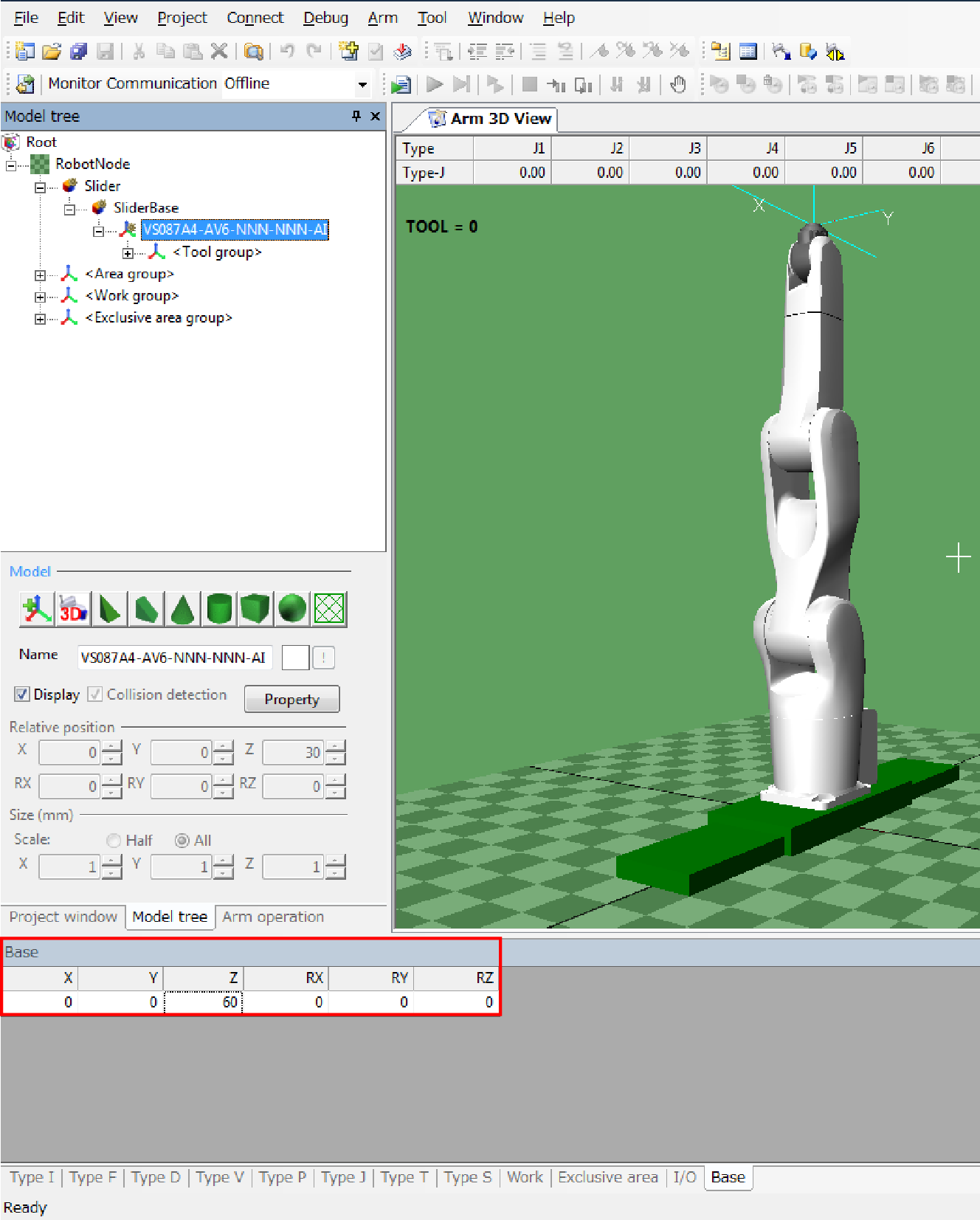
5
To put the robot model on the SliderBase, the robot position on the Z-direction needs to be changed. Since the relative motion of the robot model is impossible, change the base coordinate.
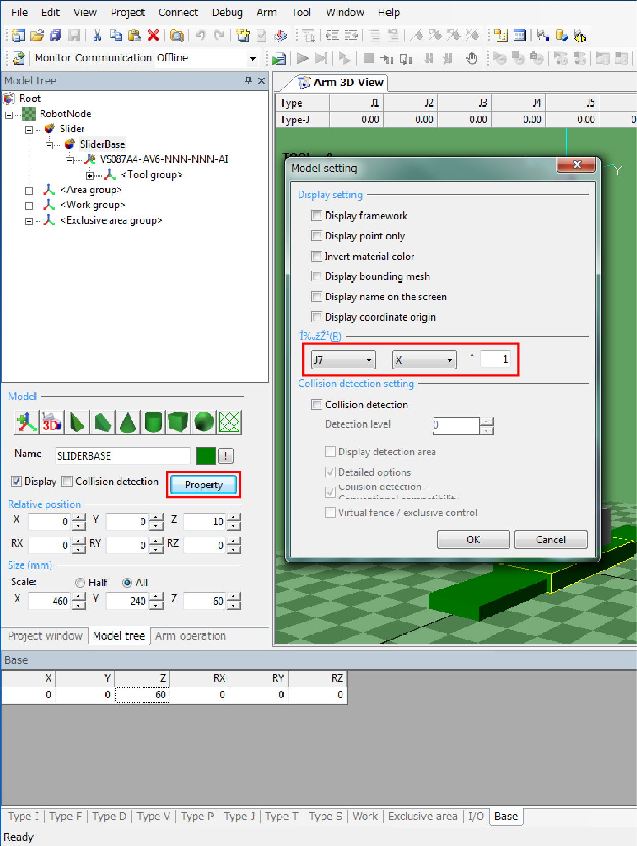
6
Select an axis you want to link, click [Property] to open [Model setting] window, and then configure [Related axis]. In this sample, specify J7-axis to move in the X-axis direction.
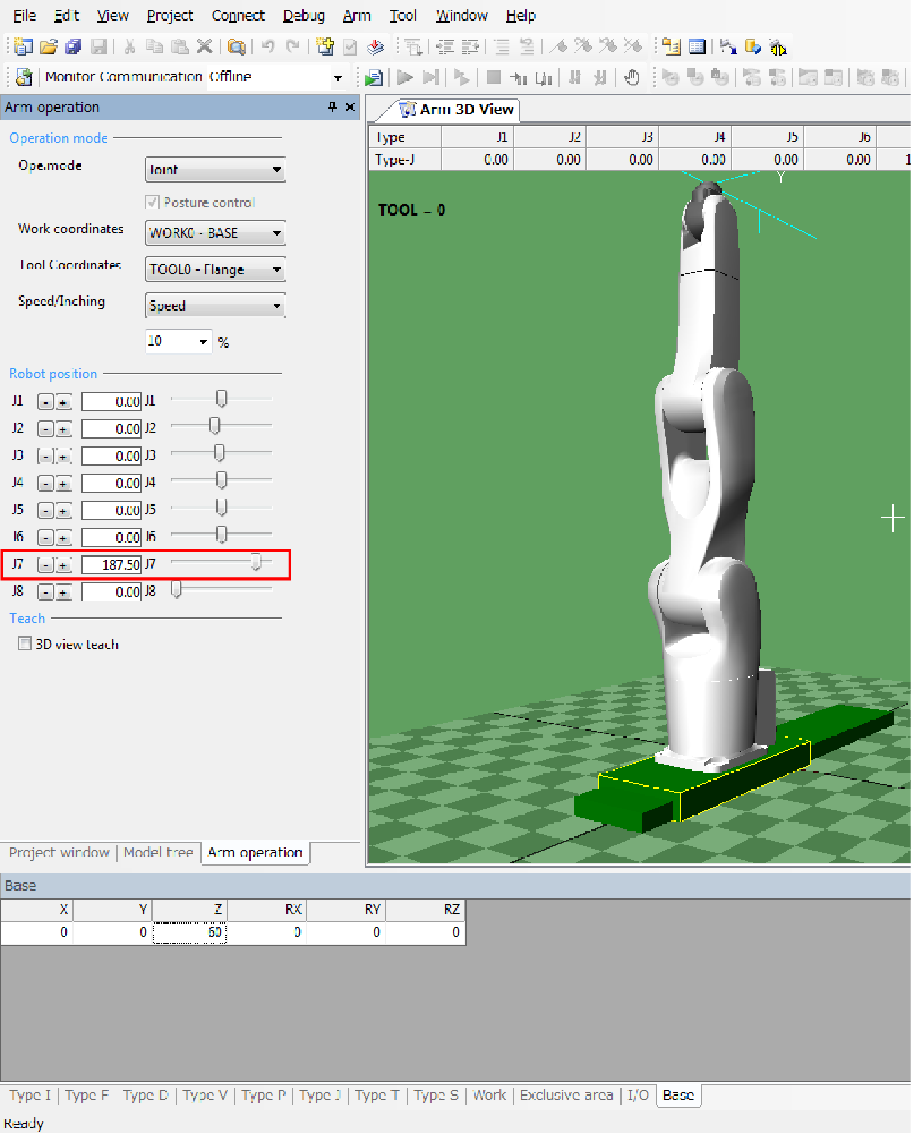
7
Select Arm operation tab. With J7-axis slider in Robot position area, check the J7-axis behavior. This completes the travel shaft setting.
ID : 2272