
ID : 2240
Creating Monitoring Models
Create a monitoring model with Arm modeling of WINCAPSIII, and then output the data to the controller.
Modeling Procedure
1
To use multiple robots, an exclusive area shall be set in the World coordinate system. Perform the Base definition.
Operation path: [Menu]– [View] – [Arm coordinate] – [Base]
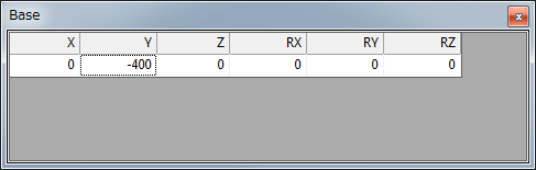
To use this function, you need to set the user parameter number [190: BASE number setting] to 1.
Once it turns to enable, the change of base coordinates can be reflected to the arm 3D view.
Even if you change the base definition on the controller, it cannot be reflected to the monitoring model.
When you change the base definition with the teach pendant, receive the base definition of controller with WINCAPSIII. Then, perform [Export exclusive control data] and send that definition to the controller.
Since WINCAPSIII cannot receive the base definition changed by Base command, it cannot be reflected to the monitoring model.
2
Create a model with Arm modeling of WINCAPSIII.
If you create a monitoring model, there are restrictions depending on monitoring models.
Model name |
Restrictions | Detail |
|---|---|---|
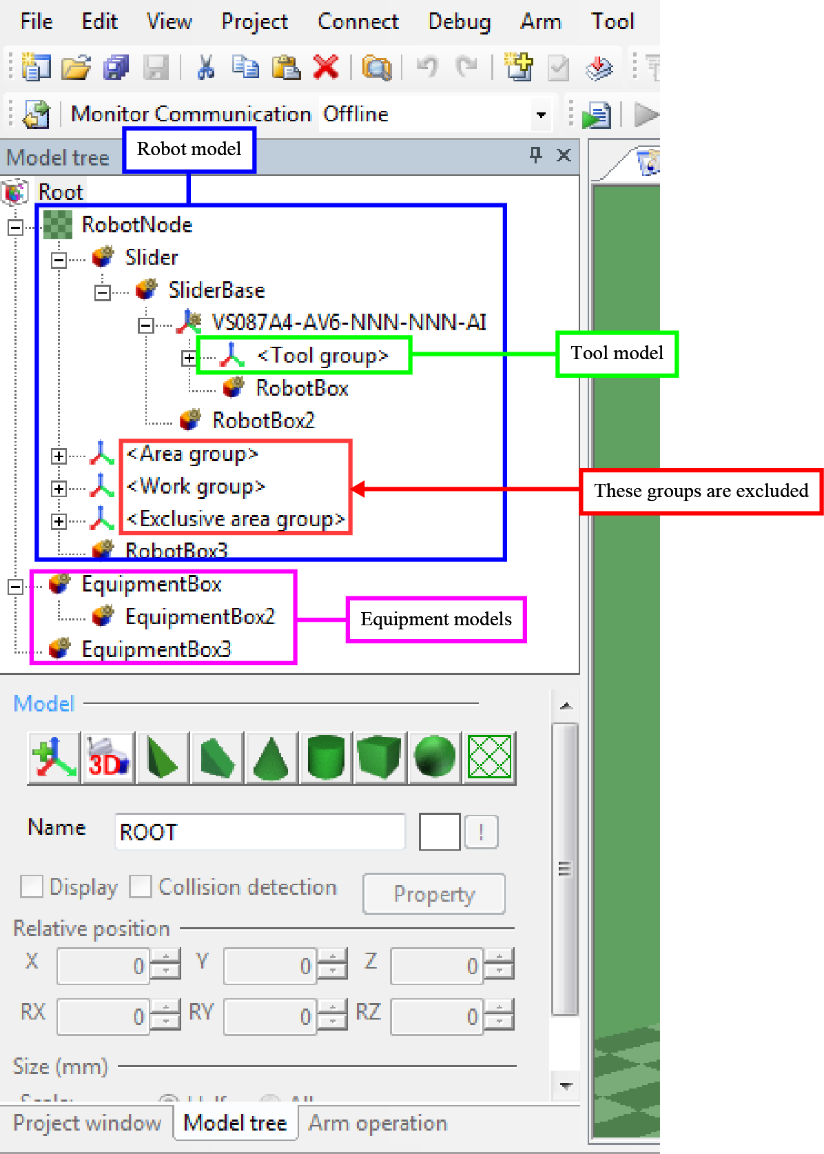
Robot model |
Objects that exist below the Robot node. Tool group, Area group, Work group, and Exclusive area group are excluded. |
- |
Tool model |
Objects that are created in the Tool group and in its subordinates. | A tool model created under Tool 0 to Tool 63 is monitored only when the Tool number where the tool model belongs is selected. |
Equipment model |
Objects that exist immediately below the Root. |
- |
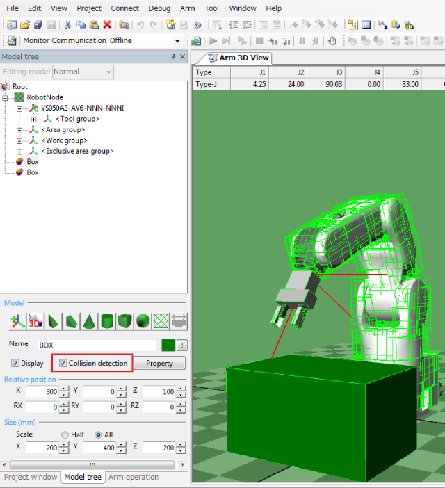
3
Select a target object, and then select the checkbox of "Collision detection".
4
Click [Property] to open Mode Setting window. Select the Virtual fence check box.
Select the "On / Off control" check box, and select a target model ID (0 to 999) in the ID box. This will allow to enable / disable the monitoring from the VirtualFence command. (Ver.2.0.* or higher)
Selecting the check box of Display detection area will display the monitoring models.
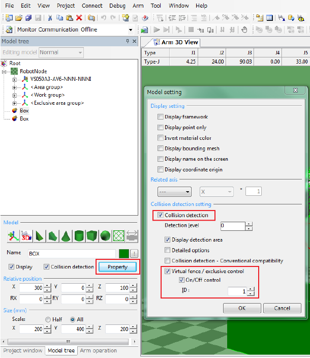
Collision detection for robot is always enabled.
5
Select the detection level.
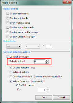
Selecting high level will realize precise monitoring though; if too high level is selected, processing time will take long, leading to the process time delay error.
6
Perform STEP2 to STEP4 for all models to be monitored.
7
Convert virtual fence data that has just created from STEP 1 to 5 to controller-processable format, and then save it.
[Menu] - [Arm] - [Export virtual fence / exclusive control data]
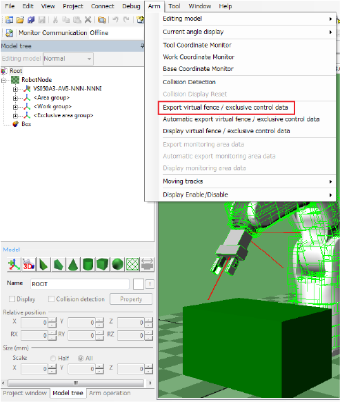
You can check the exported virtual fence data by selecting the menu [Arm] - [Display virtual fence / exclusive control data].
8
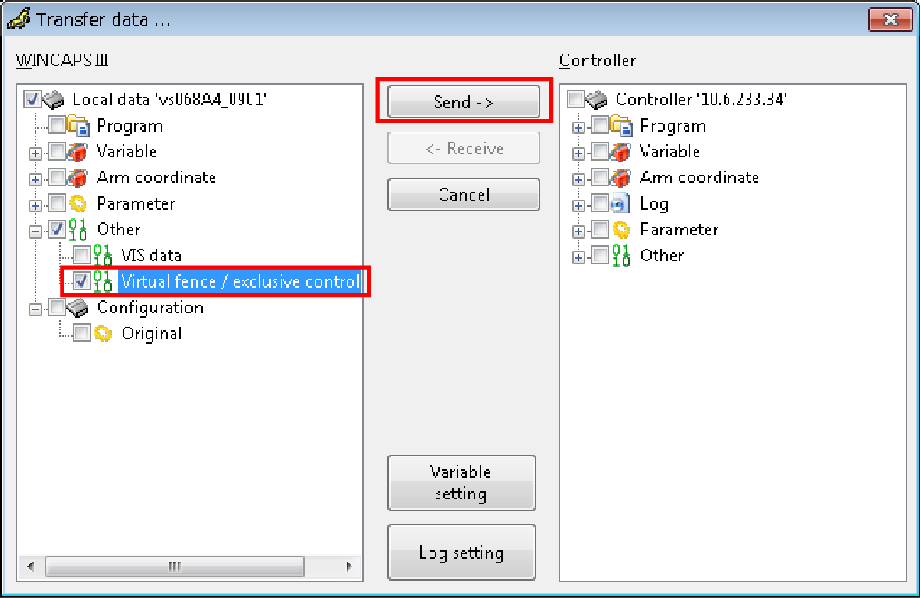
Send the data to the controller.
For information on how to establish communication between WINCAPSIII and robot controller, please refer to "Communications Settings" and "Data Transfers" in "WINCAPSIII GUIDE".
Reboot the robot controller after sending the data.
- To perform this step, the robot controller and WINCAPSIII must be connected with a cable.
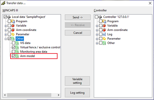
For information on how to connect, please refer to "Link with Robot Controller" in "WINCAPSIII GUIDE". - When you select the check box of "Arm model", you can send the creation source model data of virtual fence / exclusive control data to the controller. However, if the storage area is insufficient in the controller, the item "Arm model" will not be displayed.
This function is available in Ver.2.11.* or higher.
9
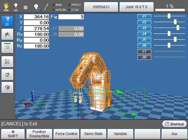
With a teach pendant, open the Arm window.
To display a monitoring model, from the Arm Display Setting window, set desired objects (Arm, Tool, Work, and Area) to "Display", from the Virtual Fence Setting window, set "366: Virtual fence setting" to "1: Enable", and then reboot the controller.
Robot models are colored orange, always-monitored models are colored light orange, and models which monitoring state can be changed are colored green (when the monitoring is enabled).
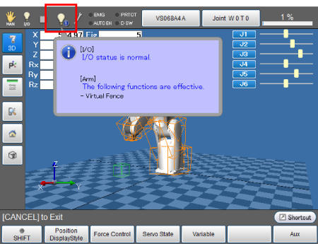
If the Virtual fence or the exclusive control is enabled, the [I/O status/Arm status] icon on the status bar will be changed to the following figure. Tapping the icon will display the detailed information of the icon.
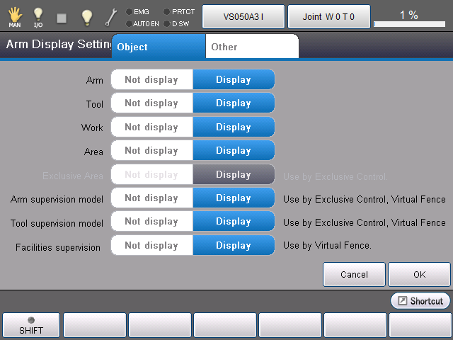
Displaying / Hiding the Monitoring Models
Monitoring models are displayed/hidden by the following entry.
Operation path: [Menu] - [F2: Arm] - [F6: Aux] - [F7: DisplaySettings]
Select [Display] or [Not display], and then press [OK].
ID : 2240